SA_HF_intern_0194307-02_eng.pdf - 第30页
3 Serv ice Gan tri es SIPL ACE HF-Ser ies Replacing the T railing Cable [03013940 -xx] 3-16 0019 43 07- 02 Is su e 1 1/ 2004 Copy ri gh t © 2 004 S ie m ens 5 5 1 4 3 2 Disconnect the flat ribb on cable fro m the head …

SIPLACE HF-Series
Replacing the Trailing Cable [03013940-xx]
Service
Gantries
3
Copyright © 2004 Siemens 00194307-02 Issue 11/2004 3-15
Remove the necessary cable ties at the gantry interface (2) and
disconnect the flat ribbon cable.
Disconnect the motor, proximity switches, read head and
temperature sensor cables from the gantry interface (2).
NOTE
The gantry interface board is installed on the cable clamp of the new
trailing cable.
Remove the cooling tubes (4) from the Y-axis motor.
Undo the screws fastening the pressure plates (3) at the power
track chain. Please note that the screws have been secured
with loctite.
NOTE
Only undo the fastening screws. The clamps for the flat ribbon cable
remain in place.
3
Service
Gantries
SIPLACE HF-Series
Replacing the Trailing Cable [03013940-xx]
3-16
00194307-02 Issue 11/2004 Copyright © 2004 Siemens
5
5
1
4
3
2
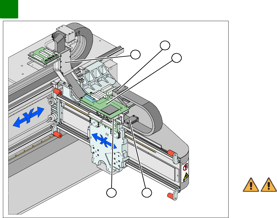
Disconnect the flat ribbon cable from the head board (1).
Undo the screws fastening the pressure plate (3) to the head
mount and the two screws on the gantry (5).
NOTE
Only undo the fastening screws. The clamps for the flat ribbon cable
remain in place.
Remove the head board (1). This provides access to the
pneumatic distributor (2) below.
NOTE
Mark the installation position of the contact disks and spacer bolts
and take care not to lose them. These will need to be correctly
replaced later.
Remove the hoses from the pneumatic distributor (2).
WARNING
Risk of injury to hands. Press the lock in with a suitable tool and
extract the hose out with hose pliers.
TIP
Cut the hoses with wire cutters and then dismantle the
pneumatic distributor. It is easier to disconnect the hoses when
they are no longer installed.
SIPLACE HF-Series
Replacing the Trailing Cable [03013940-xx]
Service
Gantries
3
Copyright © 2004 Siemens 00194307-02 Issue 11/2004 3-17
1
1
2
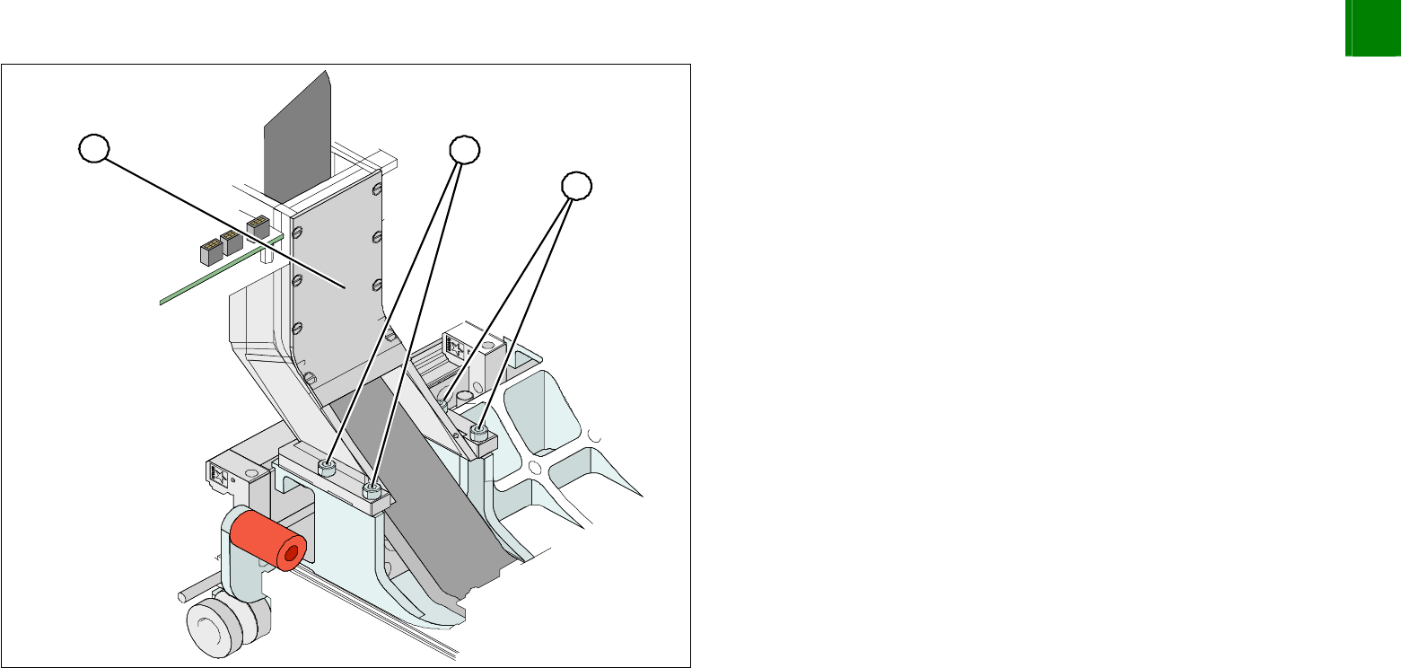
Undo the 4 screws (1) fastening the trailing cable console (2)
and carefully remove the complete trailing cable from the
machine.
NOTE
The fastening screws have been secured with Loctite 242.
If you have dismantled the pneumatic distributor, now
disconnect the hoses.