SA_HF_intern_0194307-02_eng.pdf - 第36页
3 Serv ice Gan tri es SIPL ACE HF-Ser ies Replacing the Y -Drive (Prima ry) [03006768 -xx] 3-22 0019 43 07- 02 Is su e 1 1/ 2004 Copy ri gh t © 2 004 S ie m ens 3.1.3 Replacing the Y-Dri ve (Primary ) [0300 6768-x x] Dis…
SIPLACE HF-Series
Replacing the Trailing Cable [03013940-xx]
Service
Gantries
3
Copyright © 2004 Siemens 00194307-02 Issue 11/2004 3-21
5
1
3
2
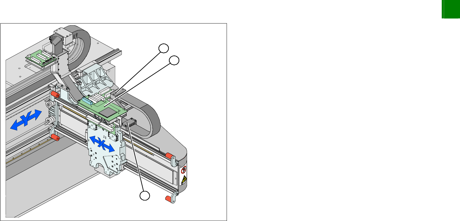
Reconnect the cooling tubes to the Y-axis motor.
Install the 3 pressure plates (1) on the gantry and head mount
(2).
Install the head board (3). Make sure you do not lose the
contact disks or spacer bolts.
Plug in all connections/terminals. Observe the correct connector
assignment.
Fasten new cable ties at the original points.
Replace all cover plates.
3
Service
Gantries
SIPLACE HF-Series
Replacing the Y-Drive (Primary) [03006768-xx]
3-22
00194307-02 Issue 11/2004 Copyright © 2004 Siemens
3.1.3 Replacing the Y-Drive (Primary) [03006768-xx]
Disassembly
2
3
1
3
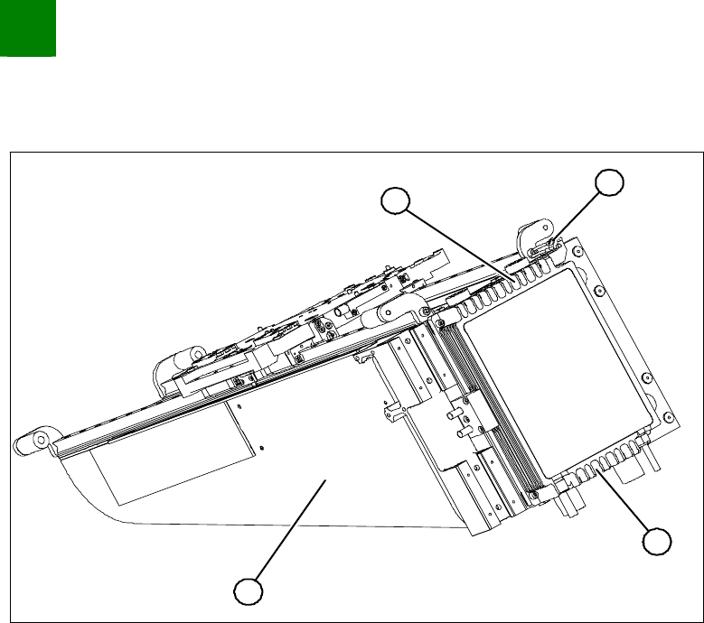
Dismantle the gantry and put it in a suitable place (1).
Remove the cable ties holding the connection cable.
Remove the proximity switch mount (2) and proximity switches.
Undo the 16 fastening screws (3). Make sure you do not lose
the insulating plates underneath the screws. These must be
replaced after completing service work.
CAUTION
The fastening screws have been secured with loctite.
SIPLACE HF-Series
Replacing the Y-Drive (Primary) [03006768-xx]
Service
Gantries
3
Copyright © 2004 Siemens 00194307-02 Issue 11/2004 3-23
Installation
2
1
4
3
2
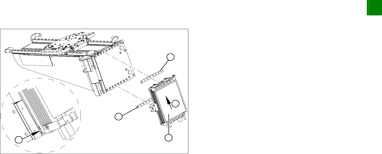
Loosely fasten the new Y-drive (1) with the screws and
insulating plates (2) provided. Use Loctite 241 to secure the
screws.
Press the motor upwards (3) and tighten the two middle screws
(at the top and bottom).
Check that the ends of the insulating plates (4) do not jut out. If
necessary, press these back in with a suitable tool (e.g.
screwdriver) and then tighten the screws.
Tighten all 16 fastening screws with a torque wrench (5.5 N).
Install the proximity switch mount and proximity switches.
Fasten the connection cable so that it will not be in the way
when installing the gantry.
Install the gantry and the trailing cable.