SA_HF_intern_0194307-02_eng.pdf - 第43页
SIPL ACE HF-Ser ies Replacing the X -Drive (Prima ry) [00375245 -xx] Serv ice Gan tri es 3 Copy ri ght © 200 4 S ie m ens 0019 43 07- 02 Is su e 1 1/ 2004 3-29 1 1 1 2 2 M4 x 8 M4 x 18 M4 x 14 1 Unscrew the remaini ng …
3
Service
Gantries
SIPLACE HF-Series
Replacing the X-Drive (Primary) [00375245-xx]
3-28
00194307-02 Issue 11/2004 Copyright © 2004 Siemens
1
2
2
1
2
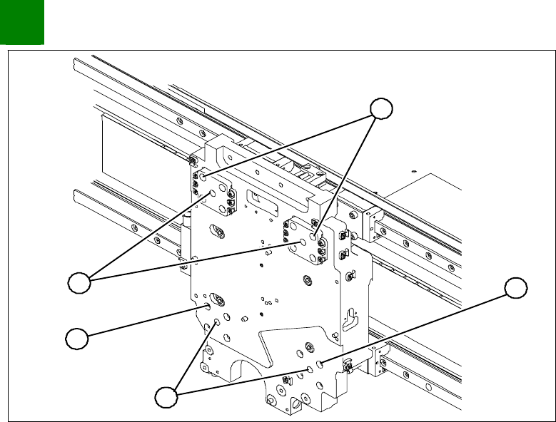
1. Insert 4 forcing screws.
2. 4 M4x60 locking screws
Screw 1 forcing screw (1) into each side, tightening until it
reaches the plate.
Remove one fastening screw (2) from each of the 4 sides.
Replace the fastening screw with a M4x60 locking screw. The
motor has now been secured against falling.
SIPLACE HF-Series
Replacing the X-Drive (Primary) [00375245-xx]
Service
Gantries
3
Copyright © 2004 Siemens 00194307-02 Issue 11/2004 3-29
1
1
1
2
2
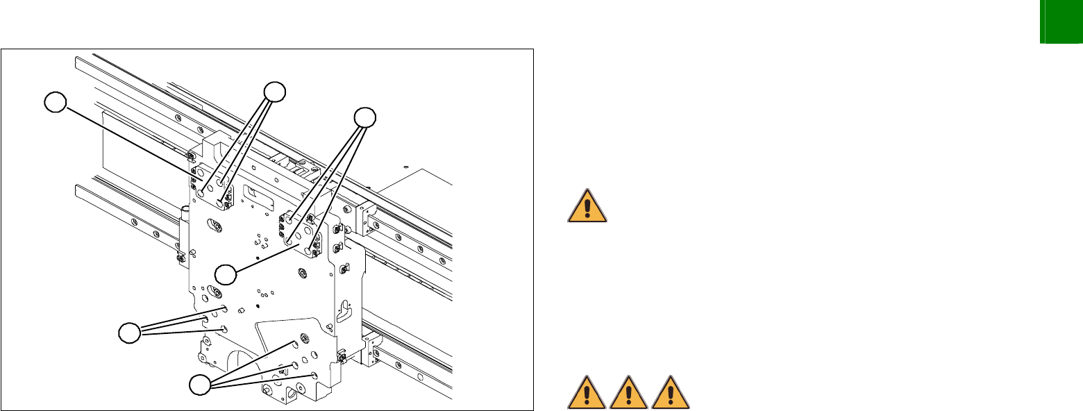
M4 x 8
M4 x 18
M4 x 14
1
Unscrew the remaining 12 fastening screws (1).
CAUTION
The screws are of different lengths. These will need to be correctly
replaced later. To make sure there are no mistakes, mark the
positions of the screws.
CAUTION
Do not loosen or unscrew the screws secured with loctite on the Z-
axis compensation (2).
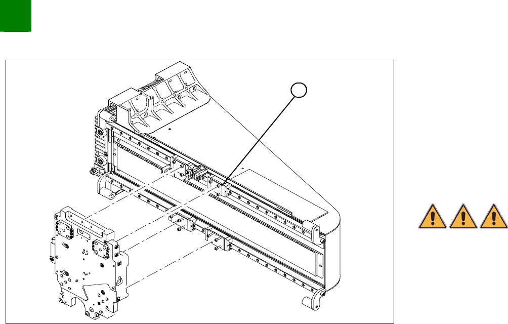
Tighten the forcing screws alternately so that the X-drive is
evenly pushed away from the magnetic field of the magnetic
strip. The X-drive is held by the 4 locking screws.
DANGER
Risk of serious or fatal injuries through trapping limbs.
Place a foam mat between the X-drive and the magnetic strip for
your own safety.
For additional safety, leave the forcing screws in place until the X-
drive has been removed from the machine.
Once the X-drive has left the strong magnetic field, it can be
taken out of the machine. To do this, remove the 4 locking
screws.
3
Service
Gantries
SIPLACE HF-Series
Replacing the X-Drive (Primary) [00375245-xx]
3-30
00194307-02 Issue 11/2004 Copyright © 2004 Siemens
Installation
1
Clean the contact surface of the guide slide (1) with a dressing
stone (oil stone). Then wipe the surface clean with ethanol.
Fully tighten the forcing screws on each side of the new X-drive.
Place the foam mat on the magnetic strip.
Lift the new X-drive at the guide slide and secure the drive with
the M4x60 locking screws.
Pull out the foam mat.
DANGER
Risk of fatal injuries through trapping limbs. Do not place body
members between the X-drive and the magnetic strip.
Alternately loosen the forcing screws so that they are
unscrewed evenly. The X- drive must be evenly attracted
towards the magnet on all 4 sides. While doing this, press the
X-drive downwards onto the guide slides.
Install 3 fastening screws on each side. Take care to use the
right screw lengths.
Remove the locking screws and replace with the remaining
fastening screws.
Tighten all fastening screws crosswise with a torque wrench
(2.9 N).
Install the PCB camera.