SA_HF_intern_0194307-02_eng.pdf - 第52页
3 Serv ice Gan tri es SIPL ACE HF-Ser ies Replacing the X -axis Read Head [ 03 006472] 3-38 0019 43 07- 02 Is su e 1 1/ 2004 Copy ri gh t © 2 004 S ie m ens 3.1.5.1 Adjusting the Grub Screw Adjusting the gru b screw Lo…
SIPLACE HF-Series
Replacing the X-axis Read Head [03006472]
Service
Gantries
3
Copyright © 2004 Siemens 00194307-02 Issue 11/2004 3-37
Installation
4
3
1
2
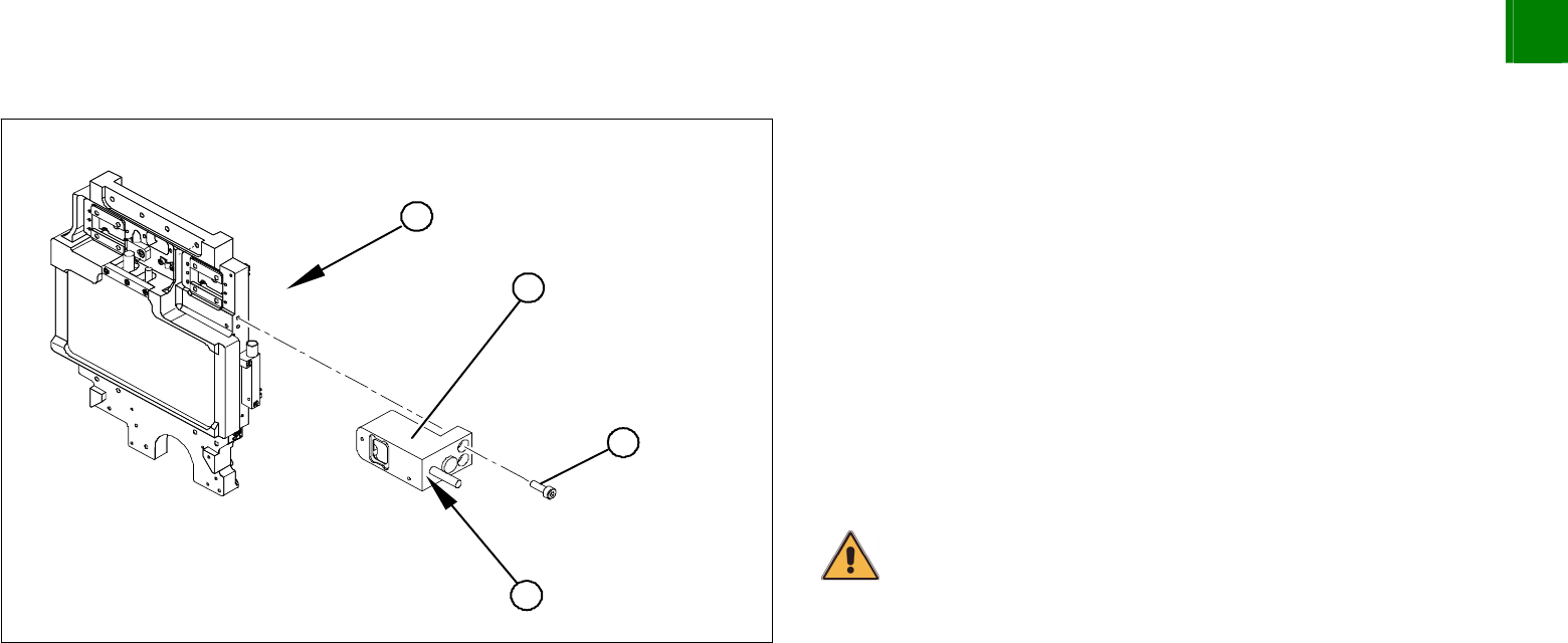
1. Head mount - front view
Clean the reading surface of the read head with a cloth and
ethanol or with a Q-tip.
Loosely fasten the read head (2) with three screws (3).
The read head must be aligned with a 0.4 mm gap to the scale.
Use the corresponding thickness gauge (plastic).
Tighten the fastening screws.
Reconnect to the electricity supply.
Make sure that the cables do not rub against anything. Fasten
them with cable ties.
CAUTION
Make sure that the axes can be moved without damaging the cables.
Check the track signals with an oscillograph.
3
Service
Gantries
SIPLACE HF-Series
Replacing the X-axis Read Head [03006472]
3-38
00194307-02 Issue 11/2004 Copyright © 2004 Siemens
3.1.5.1 Adjusting the Grub Screw
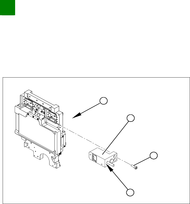
Adjusting the grub screw
Long Allen wrench size 1.5 for the grub screw on the read head
Varnished grub screw or locking varnish (Loctite No. 241)
4
3
1
2
Use the long Allen wrench (no ball head) to loosen the grub
screw (4) on the read head (2). The grub screw applies
pressure to the head mount and prevents unwanted movement
of the read head.
Remove the grub screw (4) and apply a little locking varnish
(Loctite No. 241) to it.
Screw the grub screw back in (4) until you are almost at the end
of the thread.
Install the read head (2) with the three fastening screws (3) so
that there is a gap of 0.4 mm between the read head and the
scale. Use the corresponding thickness gauge (plastic).
Tighten the grub screw (4) until you feel a slight resistance (not
too tight).
The read head is now fastened correctly.

SIPLACE HF-Series
Replacing the Guide Slide of the Y-Axis [03020303-xx]
Service
Gantries
3
Copyright © 2004 Siemens 00194307-02 Issue 11/2004 3-39
3.1.6 Replacing the Guide Slide of the Y-Axis [03020303-xx]
NOTICE!
If the guide slides need to be replaced on a machine with 2 gantries on
one side (e.g. HF-3), one of these gantries must be dismantled. Make
sure you replace the guide slides on both gantries. If there is only one
gantry on one side of the machine, this gantry need not be removed.
Tools and parts
4 or 8 guide slides [03020303-xx]
Screws and nut holders (order number 666400 from 2004 Hoffmann Catalogue)
Torque wrench
Cable ties
Blue covers [00355787-xx]
4 transportation locks for the gantry [03031930-xx]