DEK高级培训资料.pdf - 第125页
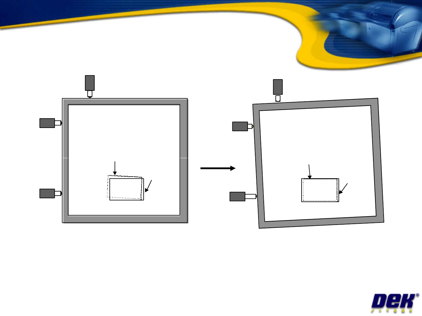
Alignment theory • The actua l distanc e moved b y the actuat ors will be de termined by: – Di stance between board and stencil – Ca mera scale and offset calibration factors Issue 2: July 2007 – Ca mera scale and offset…
Screen Image
Screen Image
Xr
Xr
Y
Y
Alignment theory
Issue 2: July 2007
Screen Image
Board
Board
Screen Image
Xf
Xf
Limits of travel: Xf,Xr = +/- 9 approx., Y = +/- 9mm approx.
Offsets: Y = +/- 1mm, X = +/- 1mm, theta +/- 1000aSec

Alignment theory
•
The actual distance moved by the actuators
will be determined by:
– Distance between board and stencil
– Camera scale and offset calibration factors
Issue 2: July 2007
– Camera scale and offset calibration factors
– Applied offsets
– Alignment weighting
– Pitch of actuator lead screw
– Step configuration of drive card
– Smallest moveable distance
• 3.41 microns currently
• 0.4 microns with micro-step introduction

Alignment Problems
This Message .... ....Occurs if .... ....and the solution is ......
Alignment close
to limits
(XF+XR) > +/-14mm
i.e. XF=8, XR = 7
Add / subtract 7.5 to board stop X dimension (but
remember squeegees and dedicated tooling
cannot be moved from centre!)
Alignment close
to limits
(XF-XR) > +/-7mm
i.e. XF=5, XR = -3
1. Check image position on screen.
2. Check rail width (excess skew)
3. Check Fiducials (other similar looking fiducial
in field of view?)
Alignment close Y > +/- 7 mm
Issue 2: July 2007
in field of view?)
4. Check Actuator Springs
5. Check Print Carriage home position
6. Check Print carriage belt tracking
7. Use ‘Customise Screen’ option
Alignment close
to limits
Y > +/- 7 mm
i.e. Y=8
Alignment Out of
Range
(XF+XR) > +/-18mm
i.e. XF=-9, XR = -9.5
Subtract 9.25 from board stop X
Dimension (but remember, squeegees and
dedicated tooling cannot be moved from centre!)
Alignment Out of
Range
(XF-XR) > +/-9mm
i.e. XF=-6, XR =3.5
1, 2, 3 and 4 above
Alignment Out of
Range
Y > +/- 9 mm
i.e. Y=9.5
1, 2, 3, 4, 5, 6 and 7 above