A10011-ASM-T47-EN-Spec-X-Serie S_DMS.pdf - 第15页
15 Placement heads General Head modularity The SIPLACE placement machines are dis tinguished by maximum flexibility in the production pr ocess. This flexibility is in part due to the head modu larity of the pl ace- ment …

14
Machine performance
Placement head types SIPLACE SpeedStar (C&P20 P)
SIPLACE MultiStar (CPP)
SIPLACE TwinStar (TH)
SIPLACE X4i S
Placement performance
For a definition of placement performance values, see the note on page 12.
Machine Placement area 1 Placement area 2 IPC value Benchmark
value
X4i S-A C&P20 P / C&P20 P C&P20 P / C&P20 P 125,000 150,000
C&P20 P / C&P20 P CPP_L/CPP_L 102,000 120,000
C&P20 P / C&P20 P CPP_H / CPP_H 100,300 118,000
CPP_L/CPP_L CPP_L/CPP_L 79,900 94,000
CPP_L/CPP_L CPP_H / CPP_H 73,950 87,000
CPP_H / CPP_H CPP_H / CPP_H 68,000 80,000
X4i S-B C&P20 P / C&P20 P CPP_H/TH 85,000 101,500
CPP_L/CPP_L CPP_H/TH 58,150 73,500
CPP_H / CPP_H CPP_H/TH 52,190 69,500
X4i S-C C&P20 P / C&P20 P TH / TH 70,900 85,500
CPP_L/CPP_L TH / TH 49,300 58,000
CPP_H / CPP_H TH / TH 43,350 51,000
CPP_H = Multistar CPP in high assembly position
CPP_L = Multistar CPP in low assembly position
15
Placement heads
General
Head modularity
The SIPLACE placement
machines are distinguished
by maximum flexibility in the
production process. This
flexibility is in part due to the
head modularity of the place-
ment machines, which allows
different placement head
variants to be configured to
suit the production require-
ments.
The SIPLACE SpeedStar
and the SIPLACE MultiStar
operate according to the
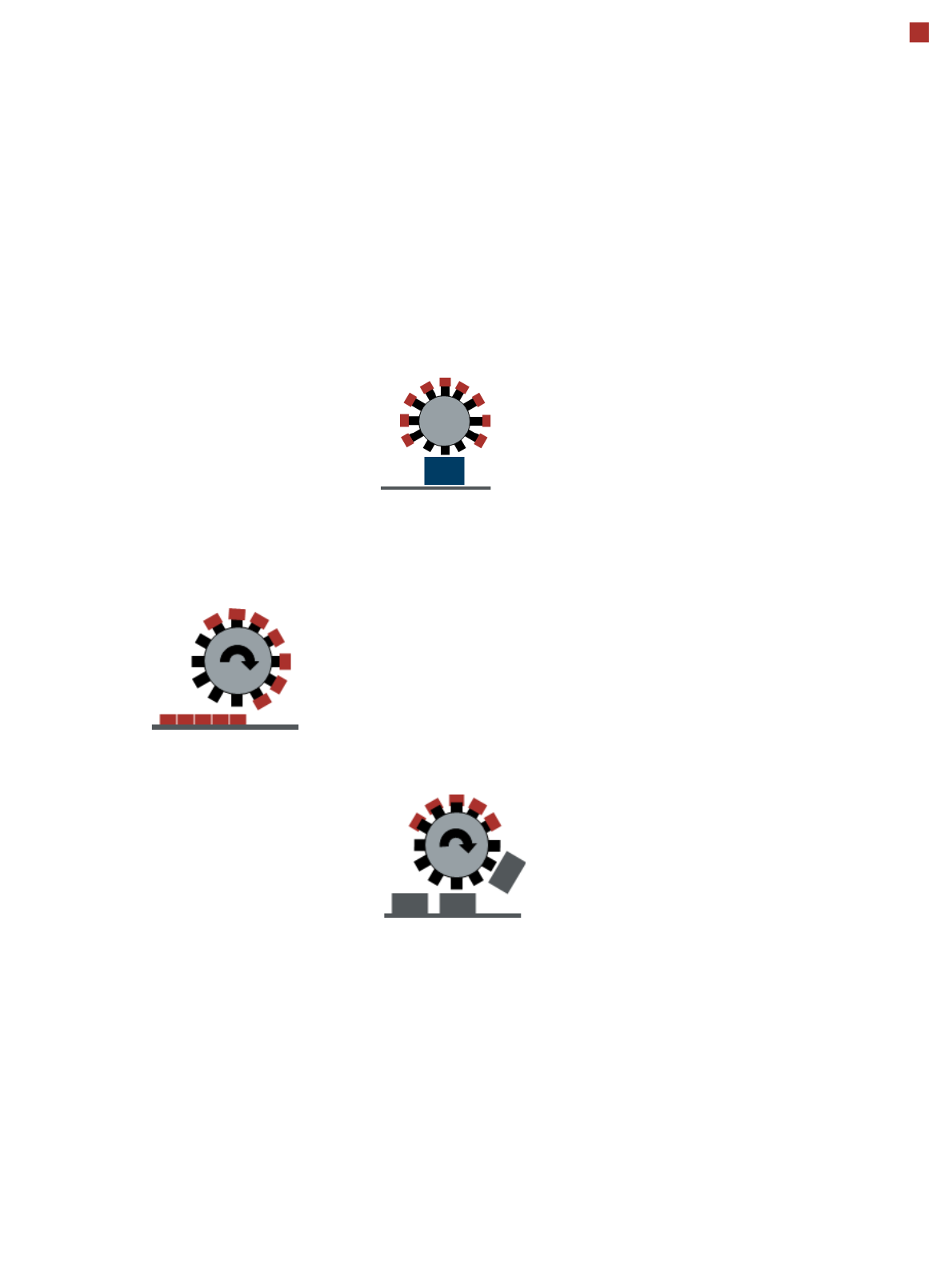
Collect&Place principle i.e.
one cycle includes pickup or
"collection" of 20 or 12 com-
ponents, their optical center-
ing on the board and their
rotation into the required
placement angle and posi-
tion. They are then placed
gently and accurately onto
the PCB. This principle is
particularly suitable for high-
speed placement of standard
components.
The SIPLACE MultiStar also
functions according to the
Pick&Place principle. Two
components are picked up
by the SIPLACE MultiStar,
optically centered on the way
to the placement position
and rotated into the required
placement angle. This princi-
ple is particularly suitable for
fast and precise placement
of large components.
The SIPLACE MultiStar uses
both the Collect&Place and
the Pick&Place principle.
Mixed Mode allows com-
bined use of these two
modes, which were previ-
ously separated from one
another, in one placement
cycle.
Pick&Place mode (Twin
Head)
The high-precision SIPLACE
TwinStar functions according
to the Pick&Place principle.
Two components are picked
up by the SIPLACE Twin-
Star, optically centered on
the way to the placement
position and rotated into the
required placement angle.
This principle is particularly
suitable for fast and precise
placement of special compo-
nents, such as those
required for grippers etc..
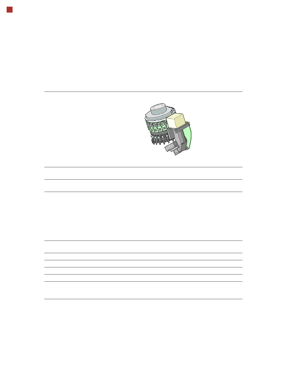
Control and self-learning
functions
The reliability of the
SIPLACE placement heads
can be enhanced even fur-
ther with various checking
and self-learning functions.
• Component sensor
Checks the presence of
the components on the
nozzle before the pickup
and placement process
• Digital camera
Checks the position of
each component on the
nozzle. This check is per-
formed in a single step,
with no extra time involved
but with optimum scan-
ning of each individual
component.
• Force sensor
Monitors the prescribed
component set-down
force.
The sensor stop proce-
dure enables compensa-
tion of height differences
during pickup and PCB
warpage during place-
ment.
• Vacuum sensor
Checks whether the com-
ponent was correctly
picked up or placed.
Collect&Place mode
Pick&Place mode
(SIPLACE MultiStar)
Mixed mode
16
Placement heads
SIPLACE SpeedStar (C&P20 P)
SIPLACE SpeedStar (C&P20 P)
with component camera
type 23
with component camera type 41
Component range
a
a) Please note that the placeable component range is also affected by the pad geometry, the customer-spe-
cific standards, the component packaging tolerances and the component tolerances.
01005 to 2220, Melf, SOT,
SOD
0201 (metric) to 2220, Melf, SOT,
SOD, Bare-Die, Flip-Chip
Component spec.
Max. height
Min. lead pitch
Min. lead width
Min. ball pitch
Min. ball diameter
Min. dimensions
Max. dimensions
Max. weight
4 mm
0.25 mm
0.1 mm
0.4 mm
0.2 mm
0.18 mm x 0.18 mm
6 mm x 6 mm
1 g
4 mm
0.08 mm
0.03 mm
0.10 mm
0.05 mm
0.12 mm x 0.12 mm
6 mm x 6 mm
1 g
Programmable set-down
force
0.5 - 4.5 N 0.5 - 4.5 N
Nozzle types 40xx 40xx
X/Y accuracy
b
b) The accuracy values are measured during the machine acceptance tests. They correspond to the condi-
tions set out in the ASM scope of service and supply.
± 36 µm/3σ ± 36 µm/3σ
Angular accuracy ± 0.5° / 3σ ± 0.5° / 3σ
Illumination levels 5 5
Standard functions High-resolution camera, vacuum sensor, force measurement, component
sensor, integrated turning station per segment, PCB warpage check, individ-
ual image of each component