A10011-ASM-T47-EN-Spec-X-Serie S_DMS.pdf - 第18页
18 Placement heads SIPLACE TwinStar (TH) SIPLACE T winSt ar with component camera type 33 (fine pitch camera) with component camera ty pe 25 (flip chip camera) Component range a a) Please note that the placeable componen…

17
Placement heads
SIPLACE MultiStar (CPP)
SIPLACE MultiStar (CPP)
with component camera type 30 with component camera type 33
(stationary camera)
Component range
a
a) Please note that the placeable component range is also affected by the pad geometry, the customer-specific
standards, the component packaging tolerances and the component tolerances.
01005 to 27 mm x 27 mm 0402 to 50 mm x 40 mm
b
b) A diagonal of 69 mm is possible during multiple measurements (e.g. 60 mm x 10 mm).
Component spec.
Max height
c
Max. height
d
Min. lead pitch
Min. lead width
Min. ball pitch
Min. ball diameter
Min. dimensions
Max. dimensions
Max. weight
c) CPP head: in low installation position (stationary component camera not possible).
d) CPP head: in high installation position.
6.0 mm
8.5 mm
0.25 mm
0.10 mm
e
/ 0.2 mm
f
0.25 mm
e
/ 0.35 mm
f
0.14 mm
e
/ 0.20 mm
f
0.4 mm x 0.2 mm
27 mm x 27 mm
4 g
e) For components < 18 mm x 18 mm.
f) For components ≥ 18 mm x18 mm.
11.5 mm
0.3 mm
0.15 mm
0.35 mm
0.2 mm
1.0mm x 0.5mm
50 mm x 40 mm
20 g
Programmable set-down
force
1.0 - 15 N
g
g) With OSC package
1.0 - 15 N
g
Nozzle types 20xx, 28xx 20xx, 28xx
X/Y accuracy
h
h) The accuracy values are measured during the machine acceptance tests. They correspond to the conditions
set out in the ASM scope of service and supply.
± 41 µm/3σ ± 34 µm/3σ
Angular accuracy ± 0.20° / 3σ
i
, ± 0.38° / 3σ
j
i) Component dimensions between 6 mm x 6 mm and 27 mm x 27 mm.
j) Component dimensions smaller than 6 mm x 6 mm.
± 0.14° / 3σ
Illumination levels 5 6
Standard functions High-resolution camera, vacuum sensor, force measurement, component
sensor, integrated turning station per segment, PCB warpage check, individ-
ual image of each component
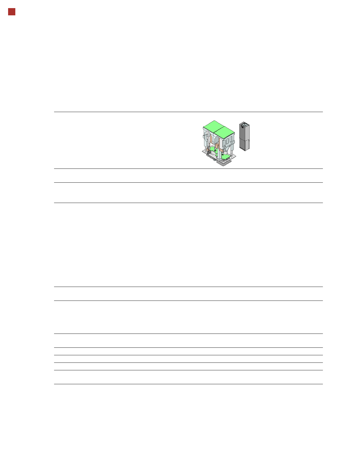
18
Placement heads
SIPLACE TwinStar (TH)
SIPLACE TwinStar
with component camera type 33
(fine pitch camera)
with component camera type 25
(flip chip camera)
Component range
a
a) Please note that the placeable component range is also affected by the pad geometry, the customer-specific standards,
the component packaging tolerances and the component tolerances.
0402 to SO, PLCC, QFP, BGA, special
components, bare dies, flip-chips
0201 to SO, PLCC, QFP, sockets,
plugs, BGA, special components, bare
dies, flip-chips, shields
Component specs
b
Max. height
Min. lead pitch
Min. lead width
Min. ball pitch
Min. ball diameter
Min. dimensions
Max. dimensions
Max. weight
c
b) If the MultiStar and TwinStar are combined in the same placement area, the maximum component height may be re-
stricted.
c) If standard nozzles are used
25 mm (higher available on request)
0.3 mm
0.15 mm
0.35 mm
0.2 mm
1.0 mm x 0.5 mm
55 mm x 45 mm (single measurement)
Up to
200 mm x 125 mm (multiple measure-
ment)
d
100 g
d) Further restrictions will apply, according to the component dimensions and the component supply. These will be auto-
matically taken into account by SIPLACE Pro.
25 mm (higher available on request)
0.25 mm
0.1 mm
0.14 mm
0.08 mm
0.6 mm x 0.3 mm
16 mm x 16 mm (single measurement)
100 g
Programmable set-down
force
1.0 N - 15 N
2.0 N - 30 N
e
e) SIPLACE High-Force Head.
1.0 N - 15 N
2.0 N - 30 N
e
Nozzle types
f
f) Over 300 different nozzles and 100 gripper types are available, with an extensive nozzle database available online.
5xx (standard)
20xx/28xx + adapter
4xx + adapter
9xx + adapter
Gripper
5xx (standard)
20xx/28xx + adapter
4xx + adapter
9xx + adapter
Gripper
Nozzle spacing for P&P
heads
70.8 mm 70.8 mm
X/Y accuracy
g
g) The accuracy values are measured during the machine acceptance tests. They correspond to the conditions set out in
the ASM scope of service and supply.
± 26 µm/3σ ± 22 µm/3σ
Angular accuracy ± 0.05° / 3σ, ± 0.05° / 3σ
Illumination levels 6 6
Standard functions Stationary fine pitch camera, vacuum sensor, force measurement, nozzle changer,
PCB warpage check, individual image of each component
19
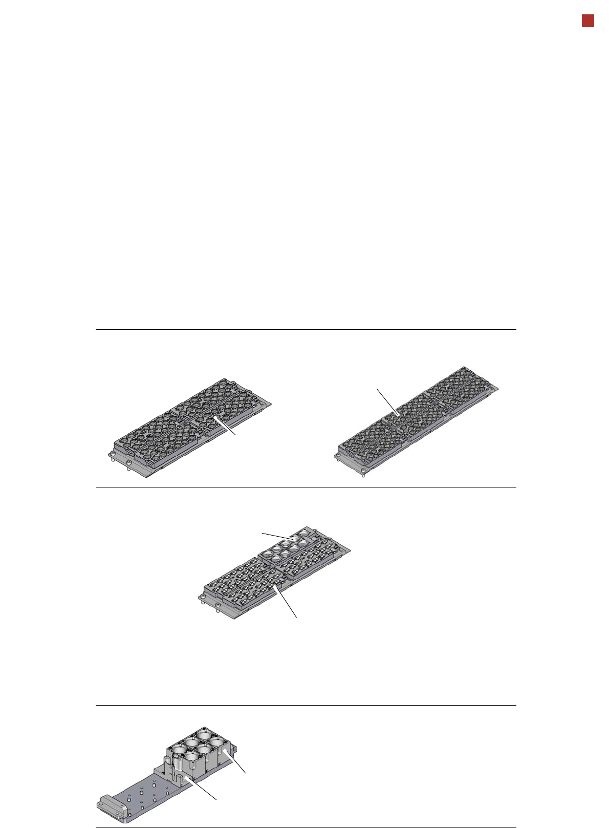
Placement heads
Nozzle changer
Nozzle changer for the SIPLACE SpeedStar (C&P20 P)
Nozzle changer for the SIPLACE MultiStar CPP
Nozzle changer for the SIPLACE TwinStar
4 magazines for 20 nozzles of
type 40xx
6 magazines for 20 nozzles of
type 40xx
Magazine for 9 nozzles of
type 28xx
Magazine for 20 nozzles of type 20xx
Magazine for two standard nozzles
Magazine for one special nozzle, gripper
Description
Nozzle changers increase the flexibility of the placement heads when it comes to processing
different components. The nozzle configuration can be rapidly adjusted to changing place-
ment jobs. Precisely defined positions and perfect nozzle seat in the garage ensure minimum
radial eccentricity on the placement head.
The nozzle changers feature a monitoring circuit. This checks whether the nozzle magazines
are seated correctly on the mount. In addition, the nozzle changer recognizes whether the
magazines are for 40xx, 20xx or 28xx nozzles by the code.