CM602规格说明书(英文).pdf - 第14页
CM602-L 2006.0515 - 9 - 4. Machine Configuration Ty pe A -0 High Spee d head (8 nozzl es) + High Spee d head (8 nozzl es) * This is the same as the previous type A. Ty pe A -1 High Spee d head (12 noz zles) + High Spee d…

CM602-L 2006.0515
- 8 -
3.2 Standard Functions
Specifications
Item
High Speed head Multi-functional head
Placement tact time
(Under optimum conditions)
* This may vary depending on
the component.
Chip 0.038 s/chip
(* 0603
(0201”)
: 0.058 s/chip)
(For type A-2)
Chip 0.048 s/chip
(* 0603
(0201”)
: 0.065 s/chip)
(For type A-0)
Chip 0.16 s/chip
(* QFP: 0.18 s/chip)
(For type B-0)
Placement accuracy
(Under optimum conditions)
* This may vary depending on
the component.
*
This data is applicable when the
placement angle is 0 °, 90 °,
180 °, or 270 °. For the other
angles, the data changes.
*
Sudden ambient temperature
changes may affect the accuracy.
0603, 1005 placement
(0201”)
±0.05 mm: Cpk
≧
1
QFP placement
±0.035 mm: Cpk
≧
1
Target component High Speed head (12 nozzles)
・
Component dimensions:
0603
(0201”)
chip to 5 mm × 5 mm
(7.3 mm or less diagonally)
High Speed head (8 nozzles)
・
Component dimensions:
0603
(0201”)
chip to 24 mm × 24 mm
・
Component thickness: Max. 6.5 mm
・
Component dimensions:
0603
(0201”)
chip to 100 mm × 90 mm
・
Component thickness: Max. 21 mm
・
Mass: Max. 30
g
PCB exchange time
0.9 s (L 240 mm × W 240 mm or less )
1.8 s (L 240 mm × W 240 mm to L 330 mm × W 330 mm)
2.3 s (L 330 mm × W 330 mm to L 510 mm × W 460 mm)
Target PCB
・
Dimension: Min. 50 mm × 50 mm to Max. 510 mm × 460 mm
(* Depending on the PCB size, special support plates are required. For further
information, please contact us.)
・
Placement Area: Min. 50 mm × 44 mm to Max. 510 mm × 454 mm
・
Thickness: 0.3 mm to 4.0 mm
・
Mass: 3
㎏
or less (After mounting, including the carrier mass.)
・
Flow direction: Left
→
Right, Left
←
Right (Selectable)
・
Reference: Front reference, Rear reference (Selectable)
* For the dual conveyor, please see “4.5 Dual Conveyor (Option)”.
Component Supply Unit
・
Taping:
8 mm tape Max. 216 inputs (Double tape feeder, small reel)
Max. 108 inputs (Double tape feeder, big reel)
Max. 108 inputs (Single tape feeder, small/big reel)
12/16 mm tape Max. 108 inputs
24/32 mm tape Max. 52 inputs
44/56 mm tape Max. 36 inputs
72 mm tape Max. 24 inputs (only Multi-functional head)
88 mm tape Max. 20 inputs (only Multi-functional head)
104 mm tape Max. 16 inputs (only Multi-functional head)
32 mm adhesive tape Max. 36 inputs
・
Bulk: Max. 108 inputs
・
Stick: Max. 24 inputs
・
Tray: Max. 20 pieces (per tray feeder)
Placement Angle -180 ° to 180 ° (In increments of 0.01 °)
Recognition
・
Recognition and offset of all applicable components
・
Offset of PCB position and orientation using recognition mark
・
Detection of vertical bending of all the leads (pins) of such as OFP and SOP
(Lead checker: Option)
CM602-L 2006.0515
- 9 -
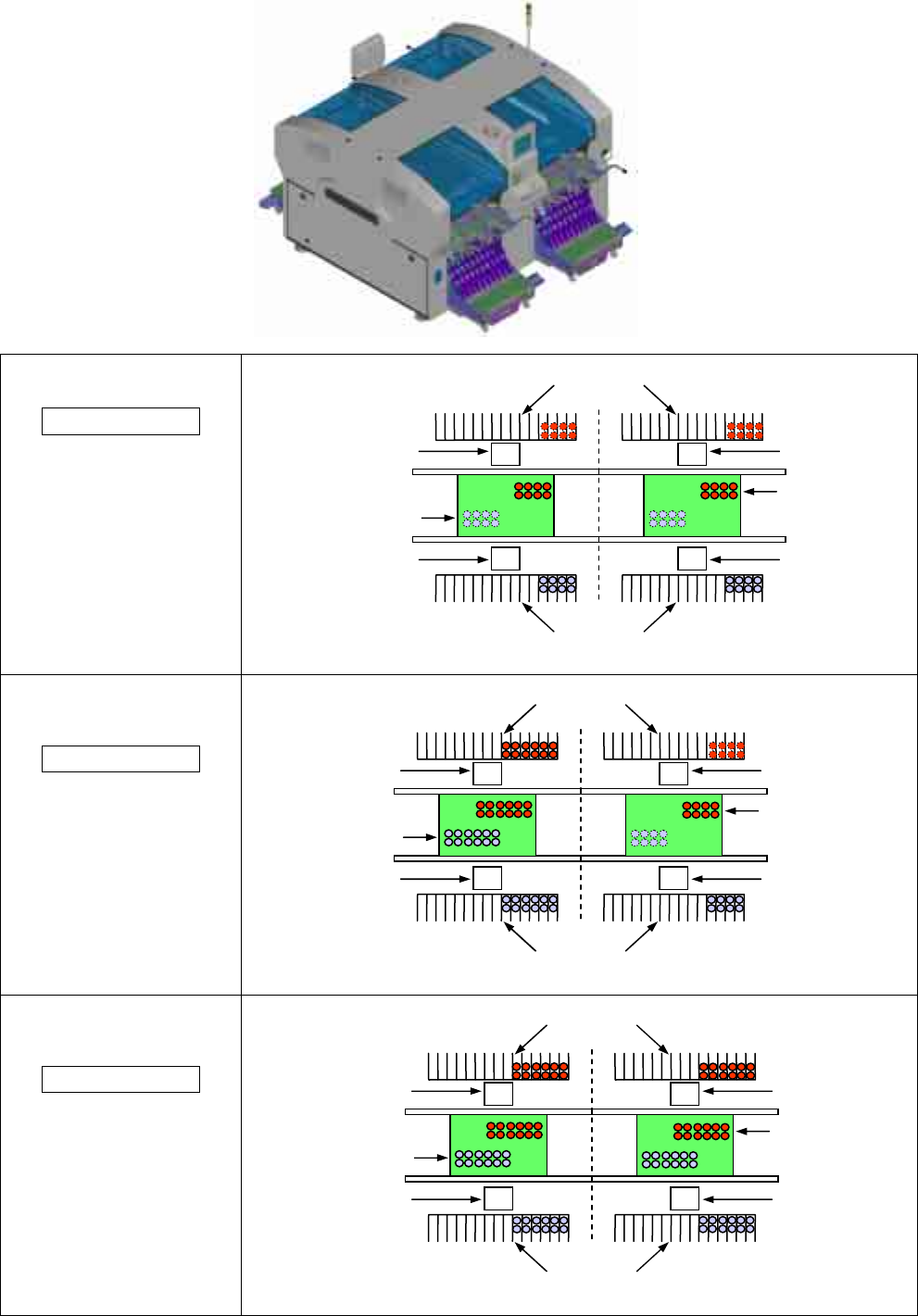
4. Machine Configuration
Type A-0
High Speed head
(8 nozzles)
+
High Speed head
(8 nozzles)
* This is the same as the
previous type A.
Type A-1
High Speed head
(12 nozzles)
+
High Speed head
(8 nozzles)
Type A-2
High Speed head
(12 nozzles)
+
High Speed head
(12 nozzles)
Line camera
(Standard)
8 nozzles head
8 nozzles head
Component Supply Unit
(feeder)
Component Supply Unit
(feeder)
Line camera
(Standard)
Line camera
(Standard)
Line camera
(Standard)
Line camera
(Standard)
12 nozzles head
12 nozzles head
Component Supply Unit
(feeder)
Component Supply Unit
(feeder)
Line camera
(Standard)
Line camera
(Standard)
Line camera
(Standard)
Line camera
(Standard)
8 nozzles head
12 nozzles head
Component Supply Unit
(feeder)
Component Supply Unit
(feeder)
Line camera
(Standard)
Line camera
(Standard)
Line camera
(Standard)
CM602-L 2006.0515
- 10 -
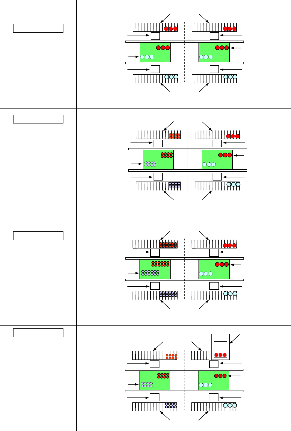
Type B-0
Multi-functional head
(3 nozzles)
+
Multi-functional head
(3 nozzles)
* This is the same as the
previous type B.
Type C-0
High Speed head
(8 nozzles)
+
Multi-functional head
(3 nozzles)
(* The High Speed heads are
located on the upstream side of
PCB flow direction.)
* This is the same as the
previous type C.
Type C-1
High Speed head
(12 nozzles)
+
Multi-functional head
(3 nozzles)
(* The High Speed heads are
located on the upstream side of
PCB flow direction.)
Type D-0
High Speed head
(8 nozzles)
+
Multi-functional head
(3 nozzles)
+
Direct tray feeder (one side)
(* The High Speed heads are
located on the upstream side of
PCB flow direction.)
* The direct tray feeder can be
connected only to the stage of
multi-functional head type.
Line camera
& Side lighting
(Standard)
3 nozzles head
3 nozzles head
Line camera
& Side lighting
(Standard)
Line camera
& Side lighting
(Standard)
Line camera
& Side lighting
(Standard)
Component Supply Unit
(feeder)
Component Supply Unit
(feeder)
Line camera
(Standard)
3 nozzles head
8 nozzles head
Line camera
(Standard)
Line camera
& Side lighting
(Standard)
Line camera
& Side lighting
(Standard)
Component Supply Unit
(feeder)
Component Supply Unit
(feeder)
Line camera
(Standard)
3 nozzles head
12 nozzles head
Line camera
(Standard)
Line camera
& Side lighting
(Standard)
Line camera
& Side lighting
(Standard)
Component Supply Unit
(feeder)
Component Supply Unit
(feeder)
Line camera
(Standard)
3 nozzles head
8 nozzles head
Component Supply Unit
(feeder)
Component Supply Unit (feeder)
Line camera
(Standard)
Line camera
& Side lighting
(Standard)
Line camera
& Side lighting
(Standard)
Component
Supply Unit
(Direct tray feeder)