CM602规格说明书(英文).pdf - 第28页
CM602-L 2006.0515 - 23 - 4.4 Feeder Carriage Configuration ■ Tape Feeder (Option) There ar e two groups of tape feeders: with or without t he joint d etection s ensor. A ccor ding to the ta pe widt h, each gro up is c la…

CM602-L 2006.0515
- 22 -
■
Recognition conditions of CSP
Placement conditions of CSP are as follows.
(Basically, placement CSP is determined and experimented after getting the sample of it, and then it is judged
to be placed or not.)
High Speed head (8 nozzles) Multi-functional head
Outside dimensions 5 mm × 5 mm to 24 mm × 24 mm 5 mm × 5 mm to 24 mm × 24 mm
Thickness 1.0 mm to 6.5 mm 1.0 mm to 21 mm
Bump pitch 0.5 mm to 1.0 mm
Bump diameter
φ
0.25 mm to
φ
0.7 mm
Bump shape Globular, cylindrical, or lead form
Materials of bump High temperature solder, eutectic solder, 42 alloy lead
Maximum bump
count
2 500
In positive grid arrangement, number of rows on most outer regions × number of columns is 50 × 50
In staggered arrangement, number of rows on most outer regions × number of columns is 25 × 25
Minimum bump
count
9
In positive grid arrangement, number of rows on most outer regions × number of columns is 3 × 3
In staggered arrangement, number of rows on most outer regions × number of columns is 3 × 3
Arrangement
of bump
The pitch and dimensions of bump shall be consistent.
(The bump missing and the staggered pattern are the same as those defined by
JEDEC and EIAJ regarding CSP.)
・
To enable the simultaneous recognition of CSP appearance and solder balls, the body shall be made of
the glass epoxy. The recognition depends on the conditions of the placement surface of solder balls (pat-
tern, with or without through hall, luster, etc.).
・
CSP which is made of ceramic and has the gold body is placed with only the contour recognition.
・
Surface of bump
The surface of bump should be free from the blur due to oxidation.
(It needs to be checked whether to recognize or not, according to the condition of oxidation.)
・
Feeding type
Fed by tape.
Fed by tray (supported by the shuttle tray feeder (option) or the direct tray feeder (option)).
■
Recognition conditions of Connector
The general conditions of placement connectors are as follows.
(Basically, placement connector is determined and experimented after getting the sample of it, and then it is
judged to be placed or not.)
High Speed head (8 nozzles) Multi-functional head
Outside dimensions 24 mm × 24 mm or less L 100 mm or less × W 90 mm or less (*)
Lead pitch 0.65 mm or over 0.5 mm or over
Lead width 0.2 mm or over
Lead shape Leads must be protruding out of the body by 1 mm or over.
Other shape
No through holes around contact pins shall exist in a vertical direction.
Contact pins shall not be exposed to the underside.
・
Feeding type
Fed by tape.
Fed by tray (supported by the shuttle tray feeder (option) or the direct tray feeder (option)).
Fed by stick (supported by the optional stick feeder).
* In the case of the placement of large sized connectors with the Multi-functional head, in addition to those, some limitations may be
imposed on the dimensions depending on the relation between the pick up position and the recognition range. For further information,
please contact us.
CM602-L 2006.0515
- 23 -
4.4 Feeder Carriage Configuration
■
Tape Feeder (Option)
There are two groups of tape feeders: with or without the joint detection sensor. According to the tape width,
each group is classified into eight types as shown below. The feed pitch is automatically set according to the
production data.
・
Without
the joint detection sensor
Feed pitch (1 pitch = 4 mm)
Feeder type
Type
width
Type
Reel
(*1)
diameter
Setting
pitch
Maximum
depth of
Boss (mm)
Maximum
Setting reel
0.5
1 2 3 4 5 6 7 8 9 10 11 12 13 14
Small 21 mm 216
8 mm
(*2)
double T/F
8 mm
Paper/
Emboss
Large 21 mm
3
108
● ●
Small 21 mm
8 mm
single T/F
8 mm
Paper/
Emboss
Large 21 mm
3 108 ● ●
Small 21 mm 15 108
12 mm Emboss
Large 21 mm 15 108
T/F for both
12 mm and
16 mm
16 mm Emboss Large 21 mm 15 108
(*3)
● ● ● ●
24 mm Emboss Large 42 mm 15 52
T/F for both
24 mm and
32 mm
32 mm Emboss Large 42 mm 15 52
● ● ● ● ● ●
●
●
15
44 mm Emboss Large 63 mm
21
(*5)
36
15
T/F for both
44 mm and
56 mm
56 mm Emboss Large 63 mm
21
(*5)
36
● ● ● ● ●
●
●
●
●
●
● ● ●
15
72 mm T/F 72 mm Emboss Large 84 mm
21
(*5)
24 ● ● ● ● ●
●
●
●
●
●
● ● ●
・
With
the joint detection sensor
Feed pitch (1 pitch = 4 mm)
Feeder type
Type
width
Type
Reel
(*1)
diameter
Setting
pitch
Maximum
depth of
Boss (mm)
Maximum
Setting reel
0.5 1 2 3 4 5 6 7 8 9 10 11 12 13 14
Small 21 mm 216
8 mm
(*2)
double T/F
8 mm
Paper/
Emboss
Large 21 mm
3
108
● ●
Small 21 mm
8 mm
single T/F
8 mm
Paper/
Emboss
Large 21 mm
3 108 ● ●
Small 21 mm 15 108
12 mm Emboss
Large 21 mm 15 108
T/F for both
12 mm and
16 mm
16 mm Emboss Large 21 mm 15 108
(*3)
● ● ● ●
24 mm Emboss Large 42 mm 15 52
T/F for both
24 mm and
32 mm
32 mm Emboss Large 42 mm 15 52
● ● ● ● ● ●
●
●
15
44 mm Emboss Large 63 mm
21
(*5)
36
15
T/F for both
44 mm and
56 mm
56 mm Emboss Large 63 mm
21
(*5)
36
● ● ● ● ●
●
●
●
●
●
● ● ●
15
72 mm T/F 72 mm Emboss Large 84 mm
21
(*5)
24 ● ● ● ● ●
●
●
●
●
●
● ● ●
(*4)
88 mm T/F
88 mm Emboss Large 105 mm 21
(*5)
20 ● ● ● ● ●
●
●
●
●
●
● ● ●
(*4)
104 mm T/F
104 mm Emboss Large 126 mm 21
(*5)
16 ● ● ● ● ●
●
●
●
●
●
● ● ●
*1: Diameter of reel
Small reel:
φ
178 mm, Large reel:
φ
178 mm to
φ
382 mm
*2:
①
two small reels or
②
the combination of a small and a large reel can be set on the 8 mm double tape feeder.
*3: Depending on the width of reel, the maximum setting count may be reduced.
*4: The 88 mm and 104 mm types are always equipped with the joint detection sensor.
*5: To use the feeders with the boss of 21 mm deep maximum, both the optional “Cutting unit for 21 mm thickness T/F” and the optional
“Feeder cart for 21 mm thickness T/F” need to be installed.
■
32 mm Adhesive Tape Feeder
(*6, 7)
(Option)
Feeder type
Type
width
Type
Reel
(*1)
diameter
Setting
pitch
Maximum height
of component
Maximum
Setting reel
Feed pitch (1 pitch = 4 mm)
32 mm
T/F 32 mm Adhesive Large 63 mm 2.8 mm 36 3 (12 mm)
*6: The adhesive tape feeder is always equipped with no joint detection sensor.
*7:
To use the adhesive tape feeders, the machine needs the required number of optional “Air supply unit for the feeder” (1 set per table).
∗∗
Remarks
∗∗
•
For 8 mm embossed tape feeders, up to 3 mm depth of boss can be supported.
•
For 12 mm tape feeders or over, up to 15 mm depth of boss can be supported; if the width of boss is
narrower than that of tape, however, the adjustments of the feeder groove width may be required for pre-
venting the tape from dropping.
In this case, the depth of boss might be limited to 13 mm or less. For further information, please contact us.
•
For High Speed head (12 nozzles) type, the versions of the software incorporated in the double tape feeder
and the feeder cart need to be updated to Ver. 5.00 or later and Ver. 1.20 or later, respectively. (Because of
the gang feed support in right and left lanes of double tape feeder.)
CM602-L 2006.0515
- 24 -
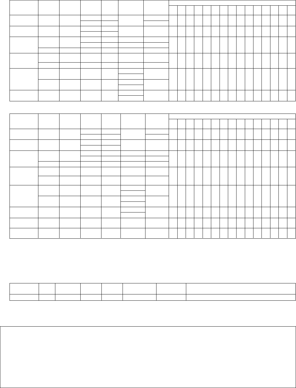
■
Intelligent Stick Feeder (Option)
The stick feeder supplies components through the stick by vibration.
Intelligent stick feeder has improved the ability to support large-sized components, in addition to the tradi-
tional merits such as high versatility (*1), quick delivery (*2), and maintenance-free (*3).
*1 It supports not only SOP, SOJ, and PLCC but also odd-shaped components such as the connector.
*2 With the feeding method that cuts out stick tips (see below), it can feed components as soon as you get them.
*3 It needs no particular maintenance except for such cleaning as dust removing.
・
Installation pitch: 84 mm
・
Maximum number of feeders installable:
Type B-0 24
Type C-0 12
(Multi-functional head-support stage)
Type C-1 12
(Multi-functional head-support stage)
* It is shared with the CM400 series, DT401, and CM212.
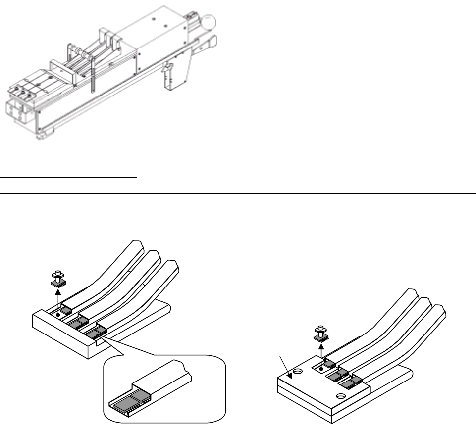
Component feeding methods
Feeding with stick tips cut out Feeding with a guide block (Option)
When components in sticks are level and stable while the
sticks are placed in a horizontal position, cut out the stick
tips so that the components will be picked up directly from
inside the sticks.
When components in sticks are not level and not stable
while the sticks are placed in a horizontal position, attach
a block (called a guide block) to solve those problems so
that the components will be picked up from the guide
block.
The guide block is created separately according to the
component dimensions to be used.
How to design the guide blocks is open to the public, so
the users can make them.
PICKUP
directly from inside sticks
Tips cut
Guide block
PICKUP
from a guide block