CM602规格说明书(英文).pdf - 第35页
CM602-L 2006.0515 - 30 - Conditions of Component The c omponents m eeting all t he follo wing c onditions ( ① to ⑦ ) can be f ed b y the shuttle tr ay feeder . ① Outside dimens ions of c ompone nt The outs ide dim ension…
CM602-L 2006.0515
- 29 -
・
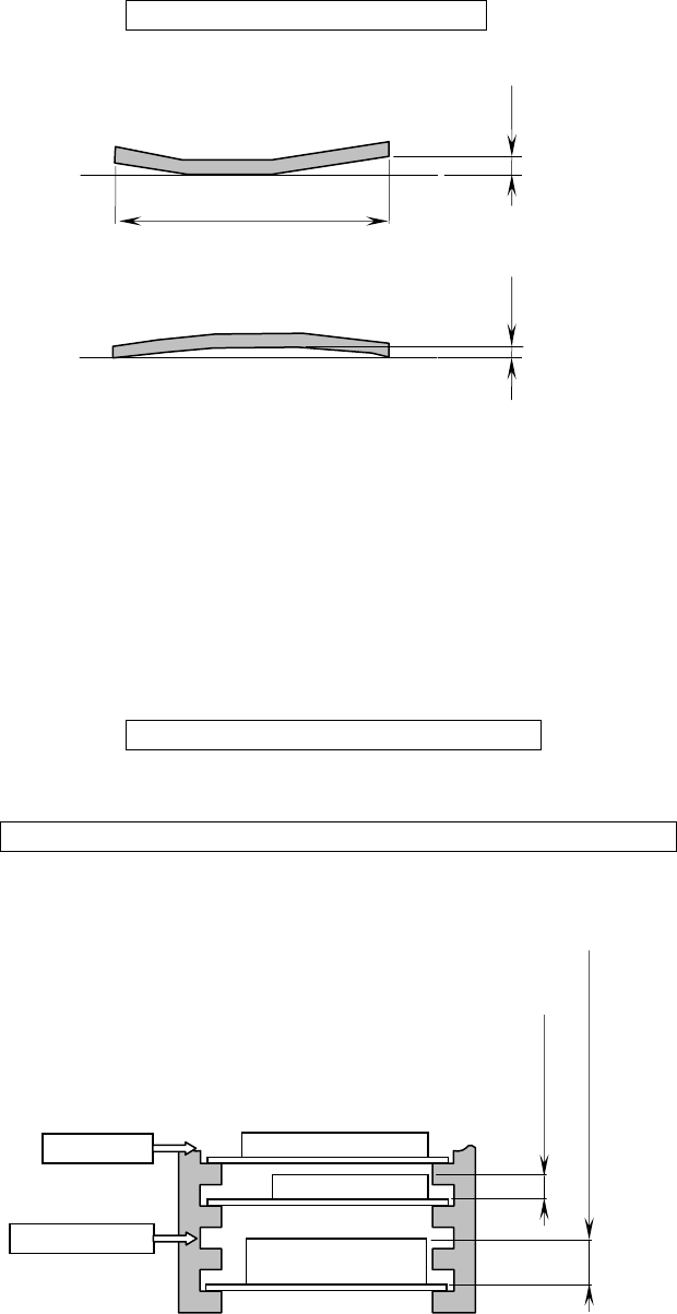
Warp: “Warp” of the tray to be loaded on a pallet shall meet the following conditions.
“
Warp” = Clearance Max. 0.5 mm
・
Type: For enough strength and dimensional accuracy, tray shall be injection molded, not vacuum molded.
(If your trays do not meet these conditions, please consult us. Then we check your sample trays and
suggest option or customization.)
・
Conditions for tray loading: The trays (components) to be loaded on a pallet and a magazine shall satisfy
the following conditions.
①
The total mass of components on a tray shall be 2
㎏
or less including the tray.
(Excluding the mass of pallet)
②
The total mass of the magazine with pallets and trays (components) shall be 20
㎏
or less.
Magazine + Pallets + Trays + Components = Max. 20
㎏
/magazine
③
If the height of the tray on a pallet exceeds 11 mm, a pallet cannot be inserted into the next higher slot
in the magazine.
Tray + Components = Max. 2
㎏
/pallet
Not insertable
Over 11 mm to 25 mm or less
11 mm or less
Insertable
Clearance
Tray
Clearance
Tray
Max. 330 mm
CM602-L 2006.0515
- 30 -
Conditions of Component
The components meeting all the following conditions (
①
to
⑦
) can be fed by the shuttle tray feeder.
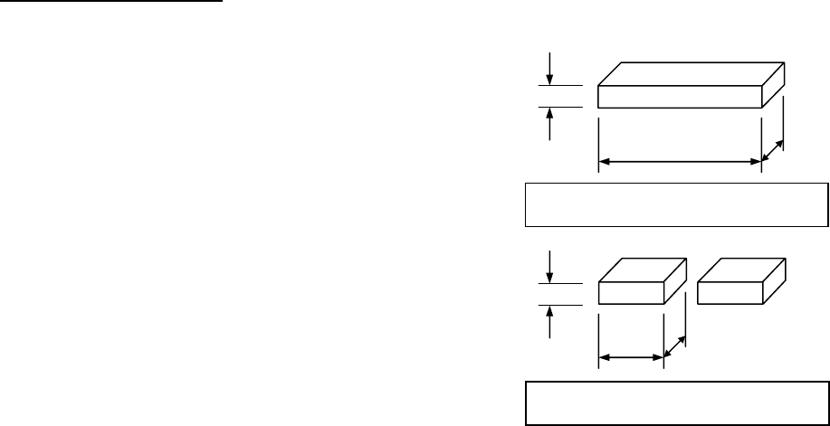
①
Outside dimensions of component
The outside dimensions of component shall be
L : 100 mm or less
W : 90 mm or less
T : 10 mm or less
For pick up and transfer by two heads
L : 38 mm or less
W : 38 mm or less
T : 10 mm or less
②
Mass of component
The mass of component shall be 30
g
or less.
③
The center of the component’s outside dimensions shall conform to its barycenter.
④
The barycenter position on the top of the component shall have a
φ
9 mm or more flat pick up face al-
lowing a stable pick up.
(In using the standard accessory
φ
6 pad nozzle)
⑤
In placement, the projection to be projected below the top of PCB shall not exist on the underside of the
component, which can be stably placed on a plane without tilting, shaking, and rolling.
⑥
The components shall be in the tray that meets its conditions.
⑦
Standard available components
(1) SOP 9 mm × 15 mm to 9 mm × 18 mm
(2) QFP 12 mm × 12 mm to 53 mm × 53 mm
(3) SOJ 11 mm × 21 mm to 11 mm × 26 mm
(4) PLCC 12 mm × 12 mm to 30 mm × 30 mm
(5) BGA 9 mm × 9 mm to 45 mm × 45 mm
(6) CSP 9 mm × 9 mm to 24 mm × 24 mm
* Except for the components mentioned above samples are required in advance to investigate the possibility of
placement.
Maximum dimensions and mass for
single component transport
100 mm
90 mm
10 mm
30
g
30
g
10 mm
38 mm
38 mm
Maximum dimensions and mass for
double component transport
CM602-L 2006.0515
- 31 -
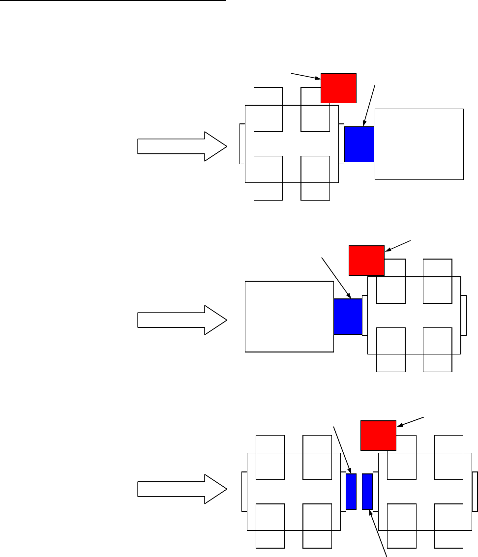
Precautions in choosing the Shuttle Tray Feeder
In choosing the shuttle tray feeder, also the extension conveyor(s) and the like need to be chosen because
that projects from the side of CM602-L.
See the following figures for the installation examples and the extension conveyors to be chosen.
①
In installing to the downstream stage
Install the working conveyor to the
downstream.
(For CM602-L, the extension conveyor
supporting shuttle trays can be selected.)
②
In installing to the upstream stage
Install the working conveyor to the upstream.
(For CM602-L, the extension conveyor
supporting shuttle trays can be selected.)
③
In installing to the upstream of the
downstream CM602-L when two
CM602-L are coupled to each other
・
Install the downstream extension
conveyor to the upstream CM602-L.
・
Install the upstream extension conveyor
to the downstream CM602-L.
Shuttle tray feeder
Working conveyor
Downstream machine
PCB flow direction
Working conveyor
Shuttle tray feeder
Upstream machine
PCB flow direction
Shuttle tray feeder
Downstream extension conveyor
PCB flow direction
Upstream extension conveyor