CM602规格说明书(英文).pdf - 第68页
CM602-L 2006.0515 - 63 - W hen exchanging t he fee der c art, it is a necess ary m inimum space. Be caref ul at t he tim e of m achine insta llation. (Unit : mm ) * T he f loor slope in the fee der c art insta llation ar…
CM602-L 2006.0515
- 62 -
■
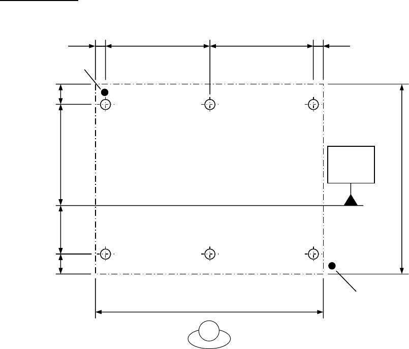
Adjust Bolt Diagram
Model: CM602-L
(Unit: mm)
Electric source
Air
0.49 MPa to 0.78 MPa
980 175
520
175
Conveyor
reference
plane
1 850
85 85
1 020 1 020
2 210
Worker side
CM602-L 2006.0515
- 63 -
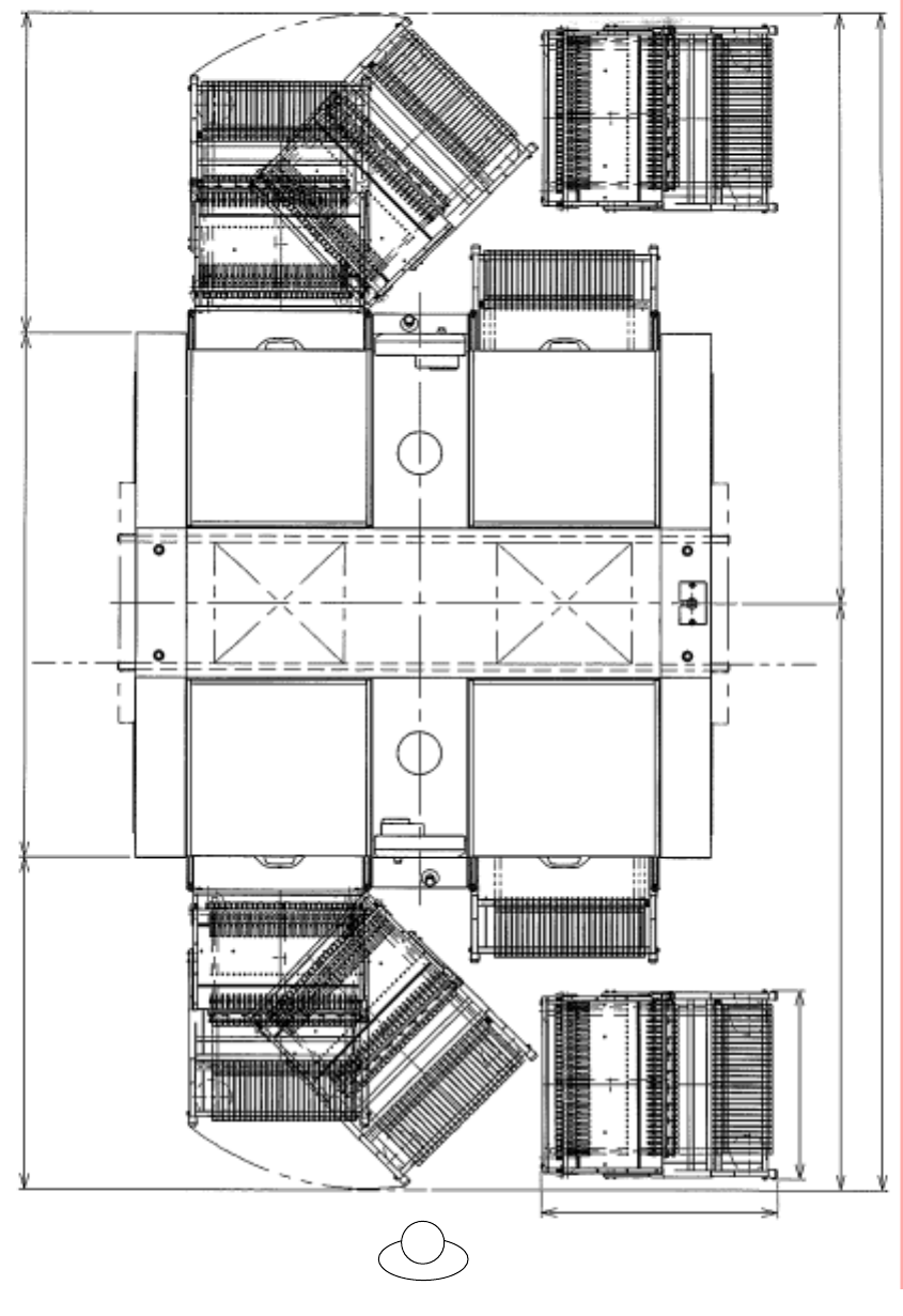
When exchanging the feeder cart, it is a necessary minimum space.
Be careful at the time of machine installation.
(Unit : mm)
* The floor slope in the feeder cart installation area needs to be 6 mm or less in the right/left direction and
11 mm or less in the forward/backward direction. If the floor slope is beyond the above limit, the feeder cart
cannot be taken in and out.
902
1 220
1 990 1 260
715
2 225
4 470
2 245
Worker side
Worker side
CM602-L 2006.0515
- 64 -
■
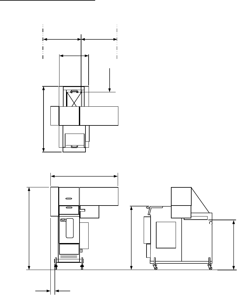
Shuttle Tray Feeder ST40S-20 (Option)
Outside dimensions (Individual)
(Unit: mm)
*1 The tray feeding height of 888 mm is a standard value when the PCB
transport height of CM602-L is 900 mm. The adjustable range is 888 mm.
*2 Center of the PCB whose size is 510 mm × 460 mm.
+65
-10
939
1 266
1 030
888
Tray feeding hight (*1)
AR: 81
BR: 76
414
A-side: 914.5
B-side: 684.5
774
(From PCB’s center *2)
1 050
PCB’s center
*2
PCB’s center
*2