CM602规格说明书(英文).pdf - 第31页
CM602-L 2006.0515 - 26 - ■ Intelligent Bulk Feeder (Option) The bulk feeder supplies com ponents in bulk ; it aligns random chips and sen ds the m to the pic kup pos itio n though vacuum suction. Intellige nt bulk feeder…
CM602-L 2006.0515
- 25 -
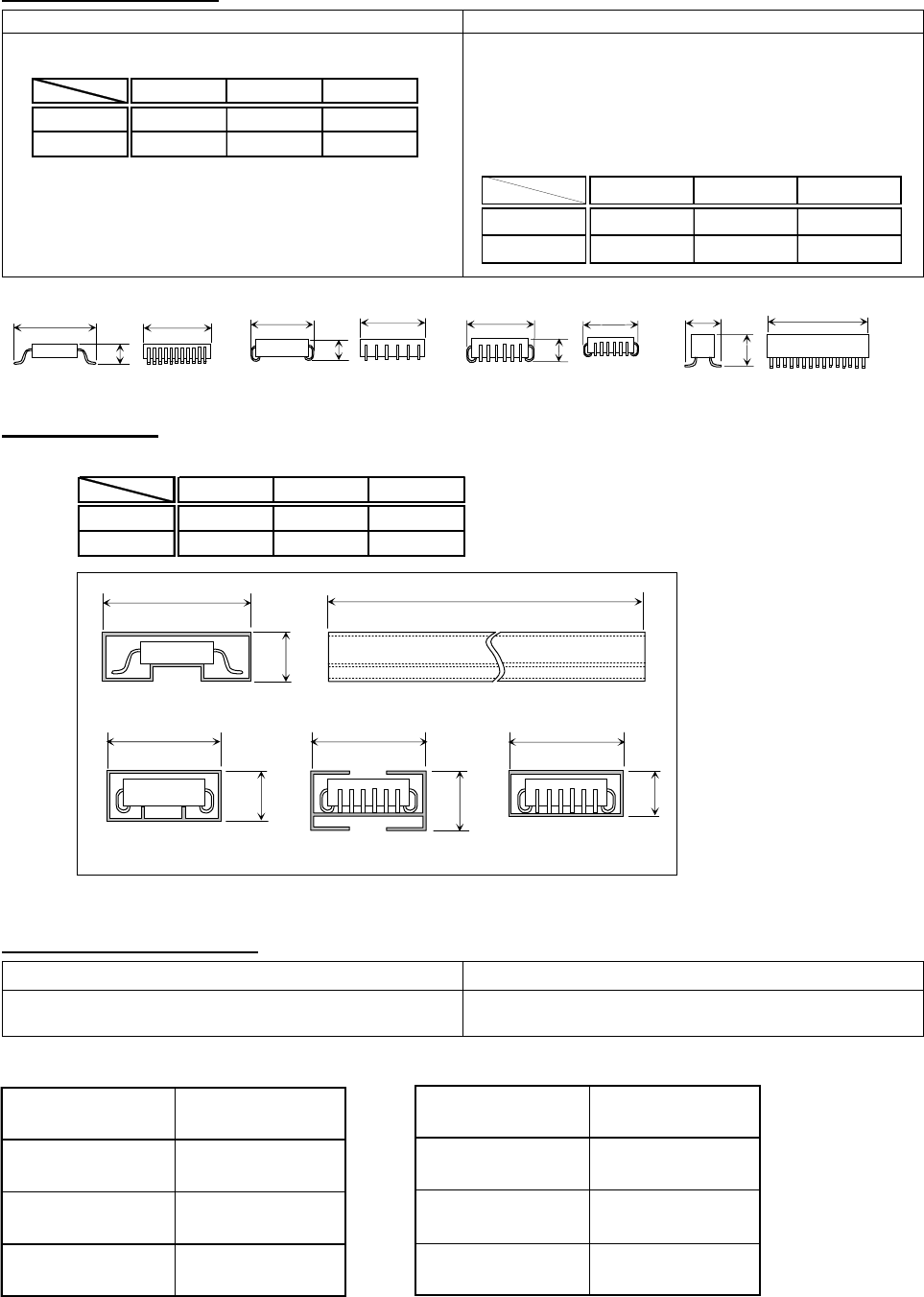
Applicable components
Standard Special
SOP, SOJ, PLCC
(All dimensions in mm)
Except for the standard component types and dimension
range, depending on the component and stick shapes,
components of up to the following dimensions may also
be used.
If using such components, you need to flow them actually
to check for feeding conditions or consult us.
(All dimensions in mm)
Applicable sticks
(All dimensions in mm)
Number of attachable sticks
Feeding with stick tips cut out Feeding with a guide block
See Table 1 for the number of attachable sticks. See either Table 1 or 2, whichever has less number, for
the number of attachable sticks.
Table 1 Table 2
* In principle, sticks to be attached shall be of the same type.
Also different types can be used; however, there are limits to the stick shape and dimension.
For details, please consult us.
WLH
Min
892.5
Max
31 31 6
WLH
Min
---
Max
31 60 25
Ws Ls Hs
Min
- 300 -
Max
34 600 28
Stick width
Ws (mm)
Number of
attachable sticks
Ws ≦ 19 3
19 < Ws ≦ 28 2
28 < Ws ≦ 34 1
Component width
W(mm)
Number of
attachable sticks
W ≦ 16 3
16 < W ≦ 25 2
25 < W ≦ 31 1
Ws
Hs
Ls
Ws
Hs
Ws
Hs
Ws
Hs
SOP
L W
H
L
W
W
L
W
L
SOJ PLCC
Connecto
r
H
H
H
CM602-L 2006.0515
- 26 -
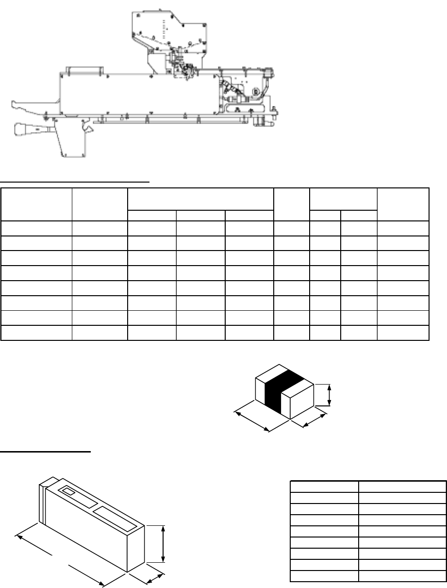
■
Intelligent Bulk Feeder (Option)
The bulk feeder supplies components in bulk; it aligns random chips and sends them to the pickup position
though vacuum suction.
Intelligent bulk feeder has a new function of vacuum ON/OFF control, in addition to the field-proven traditional
mechanism in the chip transfer section. This function stems the fouling in the vacuum systems to reduce the
frequency of maintenance by turning off vacuums when the feeders are not running. As a result, it improves
the usability and provides the higher chip-feeding quality than the traditional one.
∗
As standard, 8 L/min of air is required per intelligent bulk feeder.
・
Maximum number of feeders
installable: 108
・
Names of the models where the
feeders can be installed:
CM402-M/L
CM401-M/L
CM400-M
DT401-M/F
CM602-L
CM212-M
Feeder types & Applicable chips
*1 As for R, make contact with us in each case.
The orientation (the front or back side) of R
cannot be recognized.
*2 Shall be within our specifications.
Applicable package
・
EIAJ-standard bulk case.
■
Capacity by chip type
*
Capacity is change by manufacturer.
(Notice) When using bulk feeders, the machine needs the “Air supply unit for the feeder” (option).
36
110
12
LWT
Par chip
Pae feeder
1005C B/F 1005C 1.0 ±0.05 0.5 ±0.05 0.5 ±0.05
21
0.5 88.5 177(Min 168)
1005R
B/F 1005R
1.0 ±0.05 0.5 *2 0.35 ±0.05
21
2354
177(Min 168)
1608C B/F 1608C
1.6 ±0.1 0.8 ±0.1 0.8 ±0.1
21
0.6 66
110(Min 103)
1608R B/F 1608R
1.6 ±0.1 0.8 ±0.1 0.45 ±0.1
21
2220110(Min 103)
2012C,t=0.6
B/F 2012C,t=0.6
2.0 ±0.1 1.25 ±0.1 0.6 ±0.1
21
2.5 220
88(Min 83)
2012C,t=0.85 B/F 2012C,t=0.85
2.0 ±0.1 1.25 ±0.1 0.85 ±0.1
21
2.5 220
88(Min 83)
2012C,t=1.25 B/F 2012C,t=1.25
2.0 ±0.1 1.25 ±0.1 1.25 ±0.1
21
1.5 132 88(Min 83)
2012R B/F 2012R *1
2.0 ±0.1 1.25 ±0.1 0.55 ±0.1
21
2.5 220 88(Min 83)
No. of chips
to be aligned
Feeder type
Applicable
chip type
Installation
pitch
(mm)
Chip dimensions (mm)
Chip aligning
time (s)
-0.02
+0.05
Chip type Capacity
1005C,t=0.5 50 000
1005R,t=0.35 50 000 to 100 000*
1608C,t=0.8 15 000
1608R,t=0.45 25 000
2012C,t=0.6 10 000
2012C,t=0.85 7 000 to 10 000*
2012C,t=1.25 5 000
2012R,t=0.55 10 000
L
W
T
* JIS/EIAJ-standard or its compliant.
B/F: Bulk Feeder
(Unit : mm)
CM602-L 2006.0515
- 27 -
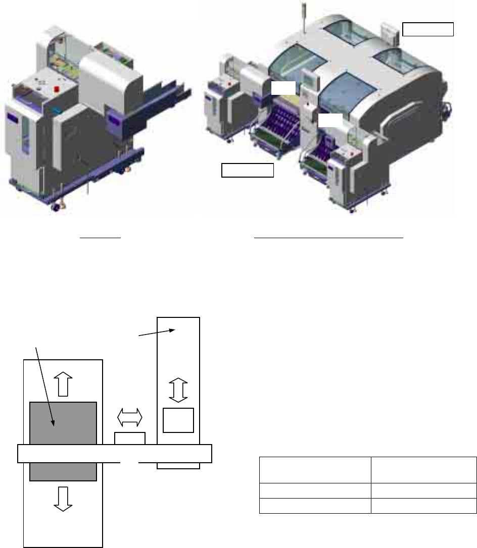
■
Shuttle Tray Feeder
ST40S-20 (Option)
Installing the shuttle tray feeder ST40S-20 onto CM602-L enables the placement of tray feeding components.
ST40S-20 can be installed on the rear side (AR and BR) of CM602-L. It cannot be installed on the front side
(AF and BF). The shuttle tray feeder can be connected only to the stage of multi-functional head type.
ST40S-20 is composed of the following three units. The unit
①
stores and selects trays, the unit
②
sends
components to the head of CM602-L, and the unit
③
acts as a bridge between these two units.
The unit
③
is placed on the top of the unit
①
that is self standing at the rear side of CM602-L.
The unit
②
is installed on the feeder cart of
CM602-L. Since there are no mechanical joints
between the units
②
and
③
, the feeder cart
can be detached or attached with ST40S-20 in-
stalled.
Please note that the unit
②
will occupy the slots
on the feeder cart. The number of slots to be
occupied is shown below.
Setting position
Number of slots
to be occupied
AR table 8
BR table 6
Since the unit
③
has two pick up heads that are raised and lowered by the air cylinder, two chips
(38 mm × 38 mm or under) can be transferred at a time.
The moving section of the unit
②
has two pick up sections equipped with the vacuum suction pads, pre-
venting chips from deviation while the components received from the unit
③
are transferred to the pick up
position of CM602-L.
①
②
③
CM602-L
pick up position
Tray
Rear side
Front side
BR
AR
Two ST40S-20 installed on CM602-L
∗
This illustration shows the machine with which two shuttle
tray feeders are connected. It is also possible to connect
only one shuttle tray feeder.
ST40S-20