_482615_RE1304003 8mm ZS feeder maint.pdf
Trained Customers Service Information 1/ 27 SI 1304003E- 00 0 = 8mm ZS feeder maintenance procedures 1 MACHINE TYPE : ZS Feeders CLASSIFICATION : Maintenance and Troubleshooting REFERENCE : Z S feeder user ’ s manual 8mm…
Trained Customers
Service Information
1/27
SI1304003E-000 = 8mm ZS feeder maintenance procedures 1
MACHINE TYPE : ZS Feeders
CLASSIFICATION : Maintenance and Troubleshooting
REFERENCE : ZS feeder user’s manual
8mm ZS feeder maintenance procedures 1
This document describes how to replace ZS feeder parts that do not require adjustments after their
replacement. The replacement procedures covered in the ZS feeder user’s manual are not covered
herein.
For replacement procedures of ZS feeder parts that require adjustments, refer to “SI1305003E-000 =
8mm ZS feeder maintenance procedures 2”.
Caution:
Those who are yet to complete required maintenance training are NOT allowed to do the service
procedures described herein.
About this document:
This document is for those who have completed required maintenance training.
Make sure to use the document under the instruction of those who have completed the maintenance training
or a YAMAHA serviceman.
YAMAHA is not responsible for any problems caused by the misuse of the document.
Make sure to thoroughly understand the contents of the document, and perform the adjustments on your own
responsibility.
All rights reserved.
About the safety:
Strictly follow the safety precautions in the “Safety” section in the “Operation Manual”.
Disclaimers:
This document contains the preliminary information subject to change in the future.
The information contained in this document represents the current view of YAMAHA on the issues discussed as of
the date of issuance. As YAMAHA must respond to changing market conditions, it should not be interpreted to be a
commitment on the part of YAMAHA, and YAMAHA cannot guarantee the accuracy of any information presented
after the date of issuance.
This document is provided for information purposes only, and it is provided without any warranties, either express
or implied.
It is the responsibility of the user to comply with all applicable copyright laws. Without limiting the rights under
copyright, no part of this document may be reproduced, stored in or introduced into a retrieval system, or
transmitted in any form or by any means (electronic, mechanical, photocopying, recording, or otherwise), or for any
purpose, without the written permission of YAMAHA.
However, this shall not be construed to limit the user’s right granted by Copyright law.
YAMAHA may have patents, patent applications, trademarks, copyrights, or other intellectual property rights
covering subject matter in this document. Except as expressly provided in any written license agreement from
YAMAHA, this document does not give users any license to these patents, trademarks, copyrights, or other
intellectual property.
The names of actual companies and products mentioned in this document may contain the trademarks of their
respective owners.
No: SI1304003E-000
ISSUED DATE: February 15, 2016

Trained Customers
Service Information
2/27
SI1304003E-000 = 8mm ZS feeder maintenance procedures 1
Table of contents
1 Required tools and replacement parts identification .............................................................. 3
2 Replacement of faulty parts (no adjustment is required after replacement) ........................ 4
2.1 Replace the reel holder bracket .......................................................................................... 4
2.2 Replace the top tape box cover ........................................................................................... 4
2.3 Replace the EL box cover ................................................................................................... 5
2.4 Replace the feeder side cover ............................................................................................. 6
2.5 Replace the cutter ............................................................................................................... 7
2.6 Replace the tail cover assy.................................................................................................. 8
2.6.1 Remove the tail cover assy ........................................................................................................ 8
2.6.2 Install the tail cover assy ............................................................................................................ 8
2.7 Replace the operation switch .............................................................................................. 9
2.7.1 Remove the operation switch ..................................................................................................... 9
2.7.2 Install the operation switch ........................................................................................................ 11
2.8 Replace the unclamp lever ................................................................................................ 12
2.8.1 Remove the unclamp lever ...................................................................................................... 12
2.8.2 Install the unclamp lever .......................................................................................................... 13
2.9 Replace the top tape box ................................................................................................... 14
2.9.1 Remove the top tape box ......................................................................................................... 14
2.9.2 Install the top tape box ............................................................................................................. 15
2.10 Replace the limit switch ..................................................................................................... 16
2.10.1 Remove the limit switch ........................................................................................................... 16
2.10.2 Install the limit switch ............................................................................................................... 18
2.11 Replace the EL box ........................................................................................................... 19
2.11.1 Remove the EL box .................................................................................................................. 19
2.11.2 Install the EL box ...................................................................................................................... 20
2.12 Replace the P/O1 roller, P4 and P5 idle gears .................................................................. 21
2.12.1 Remove the P/O1 roller, P4 and P5 idle gears ......................................................................... 21
2.12.2 Install the P/O1 roller, P4 and P5 idle gears ............................................................................. 22
2.13 Replace the P1, P2 and P3 idle gears .............................................................................. 23
2.13.1 Remove the P1, P2 and P3 idle gears ..................................................................................... 23
2.13.2 Install the P1, P2 and P3 idle gears ......................................................................................... 23
2.14 Replace the peel motor ..................................................................................................... 24
2.14.1 Remove the peel motor ............................................................................................................ 24
2.14.2 Install the peel motor ................................................................................................................ 25
2.15 Replace the splice sensor (optional) ................................................................................. 26
2.15.1 Remove the splice sensor ........................................................................................................ 26
2.15.2 Install the splice sensor ............................................................................................................ 26
3 Revision history ........................................................................................................................ 27
Trained Customers
Service Information
3/27
SI1304003E-000 = 8mm ZS feeder maintenance procedures 1
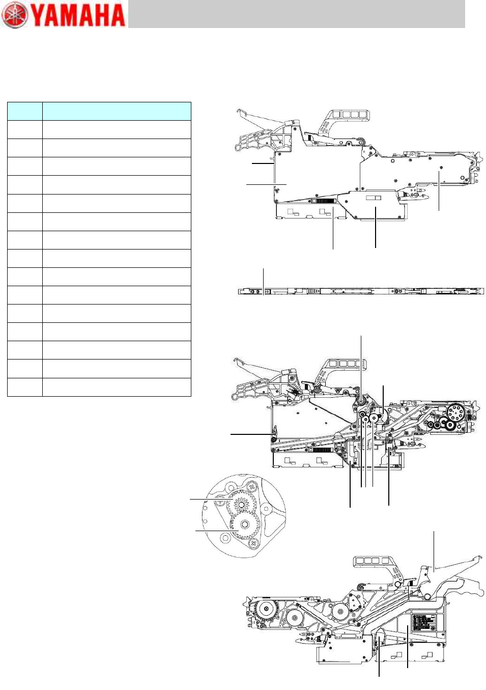
1 Required tools and replacement parts identification
YAMAHA standard tools
NSL grease
No.
Parts to replace
2-1
Reel holder bracket
2-2
Top tape box cover
2-3
EL box cover
2-4
Feeder side cover
2-5
Cutter
2-6
Tail cover
2-7
Operation switch
2-8
Unclamp lever
2-9
Top tape box
2-10
Limit switch
2-11
EL box
2-12
P/O1 roller and P4, P5 idle gears
2-13
P1, P2, P3 idle gears
2-14
Peel motor
2-15
Splice sensor (option)
2-1
2-2
2-3
2-4
2-6
2-7
2-8
2-9
2-15
2-12
2-12
2-5
2-12
2-10
2-11
2-13
2-14