_482615_RE1304003 8mm ZS feeder maint.pdf - 第9页
Trained Customers Service Information 9/ 27 SI 1304003E- 00 0 = 8mm ZS feeder maintenance procedures 1 2. 7 Replac e the operation switch 2.7 .1 Remov e t he operation sw itch Step 1 Remove the top tape box cover referri…
Trained Customers
Service Information
8/27
SI1304003E-000 = 8mm ZS feeder maintenance procedures 1
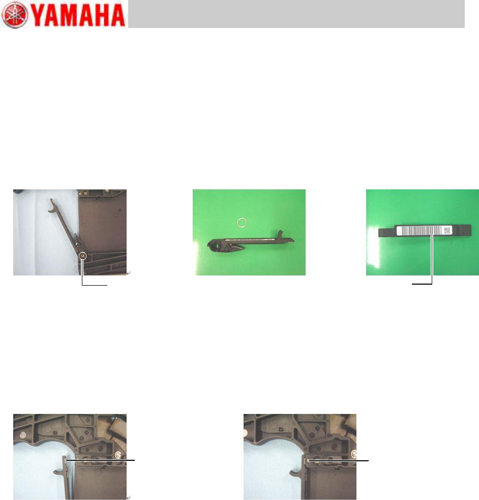
2.6 Replace the tail cover assy
2.6.1 Remove the tail cover assy
Step 1 Remove the top tape box cover referring to “2.2 Replace the top tape box cover”,
step 1.
Step 2 Remove the wave washer from the axis of the top tape box. Then pull the tail cover
assy upward to remove it from the top tape box.
Note
When placing an order for a new barcode, let us know the serial number of the feeder whose
tail cover assy is to be replaced.
2.6.2 Install the tail cover assy
Step 1 Attach the new barcode to the new tail cover assy.
Step 2 Install the tail cover assy (that includes the magnetic catch plate and cutter) to the top
tape box, and make sure it is secured with the magnet properly.
Step 3 Install the top tape box cover to the feeder body referring to “2.2 Replace the top
tape box cover”, step 2.
Wave washer
Barcode
Magnet catch plate
Magnet
Trained Customers
Service Information
9/27
SI1304003E-000 = 8mm ZS feeder maintenance procedures 1
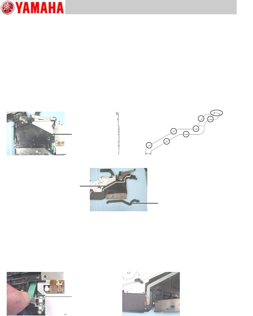
2.7 Replace the operation switch
2.7.1 Remove the operation switch
Step 1 Remove the top tape box cover referring to “2.2 Replace the top tape box cover”,
step 1.
Step 2 Press the claws of the membrane cover with tweezers or a precision driver from inside
of the top tape cover to remove the membrane cover.
Step 3 Detach the upper claws by using a precision driver or needle-nose pliers, and then
detach the lower claws by pulling the cover.
Note
When removing the membrane cover, be careful not to break the claws since they are very
small.
Step 4 Remove the EL box cover referring to “2.3 Replace the EL box cover”, step 1.
Step 5 Remove the harness of the operation switch from the connector on the feeder board
assy.
Step 6 Pull off the connection of the harness to the membrane cover side.
Note
When removing the connector, use a driver with plastic tip and take care not to damage the
feeder board assy and the connector.
Connector lock
Top tape box
Upper side
Lower side
Membrane cover
Membrane cover
ー
Operation switch
Trained Customers
Service Information
10/27
SI1304003E-000 = 8mm ZS feeder maintenance procedures 1
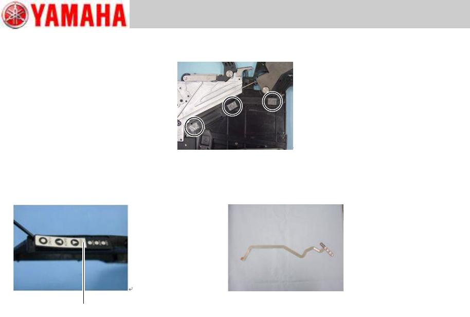
Step 7 Remove the harness from the top tape box.
The harness is attached to the top tape cover box with double-sided adhesive tape.
Step 8 Remove the operation switch from the top tape box with a precision driver, and pull out
the harness.
The operation switch is attached to the top tape box with double-sided adhesive tape.
Operation switch