_482615_RE1304003 8mm ZS feeder maint.pdf - 第26页
Trained Customers Service Information 26 / 27 SI 1304003E- 00 0 = 8mm ZS feeder maintenance procedures 1 2.15 Replace the s plice sensor (optional) 2.15.1 Remov e the splice sen sor Step 1 Remove the EL box cover referri…
Trained Customers
Service Information
25/27
SI1304003E-000 = 8mm ZS feeder maintenance procedures 1
2.14.2 Install the peel motor
Step 1 Set the new peel motor to the feeder body so that its harness is located on the lower
side.
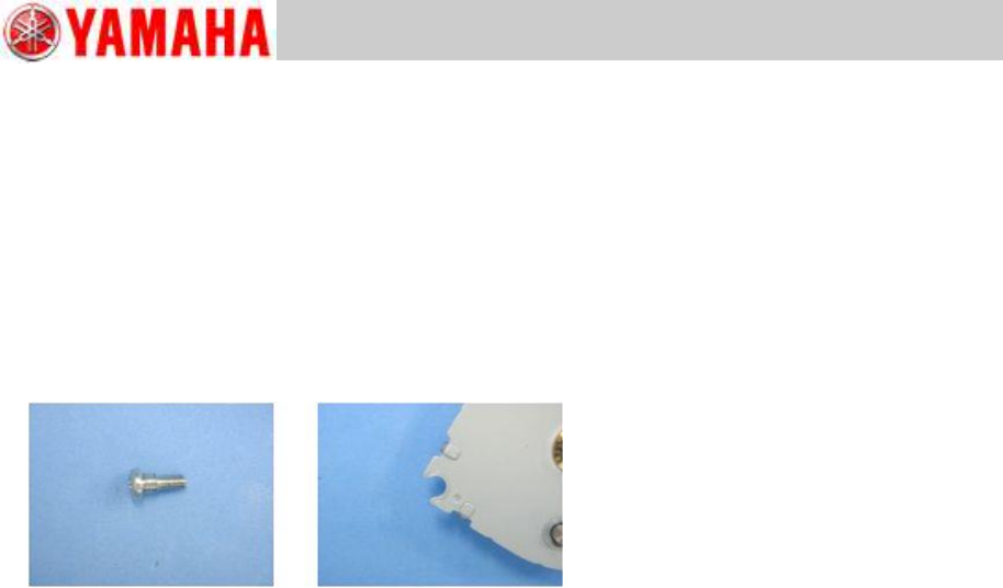
Step 2 Fasten the peel motor roughly on the feeder body with two shoulder screws using a
Phillips screwdriver (No.1). Make sure that the step of the screw and the cutout part of
the motor fit.
Step 3 Fully tighten the screws to 40Ncm.
Note
When fastening the peel motor on the feeder body, be careful not to damage the harnesses
of the ABS board and feed motor.
Step 4 Fasten the earth cable of the peel motor on the feeder body with a screw using a
Phillips screwdriver (No.1).
Tightening torque is 40Ncm.
Step 5 Connect the connector of the feed motor to the feeder board assy.
Step 6 Apply a tiny portion of the NSK NSL grease to where the P1 positioning pin and the
gear come into contact.
Note
Do not apply grease to the gear section. If the gear is contaminated with grease, wipe the
gear clean.
Step 7 Install the P1 idle gear referring to “2.13.2 Install the P1, P2 and P3 idle gears”.
Step 8 Install the feeder side cover referring to “2.4 Replace the feeder side cover”, step 2.
Step 9 Install the EL box cover referring to “2.3 Replace the EL box cover”, step 2.
Trained Customers
Service Information
26/27
SI1304003E-000 = 8mm ZS feeder maintenance procedures 1
2.15 Replace the splice sensor (optional)
2.15.1 Remove the splice sensor
Step 1 Remove the EL box cover referring to “2.3 Replace the EL box cover”, step 1.
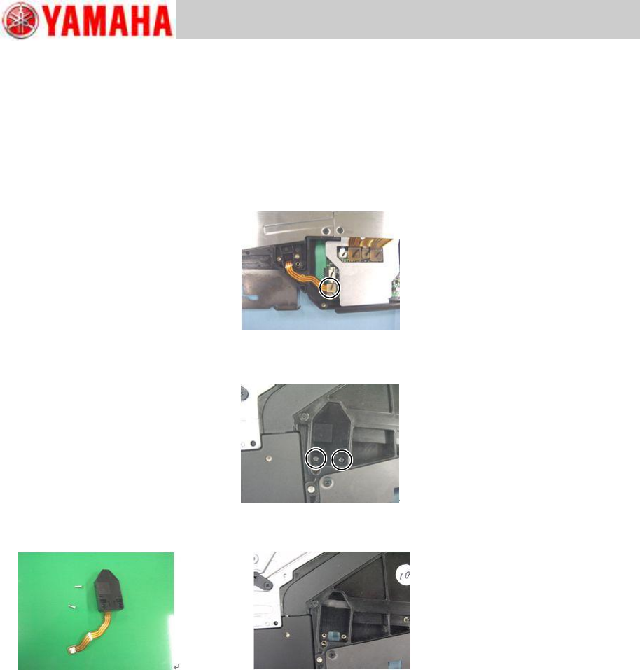
Step 2 Disconnect the splice sensor harness from the feeder board assy at the connector.
Note
When disconnecting the connector, use a driver with plastic tip and take care not to damage
the feeder board assy and the connector.
Step 3 Remove the two screws fastening the splice sensor to the top tape box with a Phillips
screwdriver (No.1).
Step 4 Pull out the harness of the splice sensor through the gap between the top tape box and
the EL box.
2.15.2 Install the splice sensor
Step 1 Insert the harness of the splice sensor into the cutout part of the EL box.
Step 2 Install the splice sensor to the top tape box with two tapping screws using a Phillips
screwdriver (No.1).
Tightening torque is 20Ncm.
Step 3 Connect the connector of the splice sensor to the feeder board assy.
Step 4 Install the EL box cover to the feeder body referring to “2.3 Replace the EL box
cover”, step 2.

Trained Customers
Service Information
27/27
SI1304003E-000 = 8mm ZS feeder maintenance procedures 1
3 Revision history
Revision No.
Updated contents
Issued Date
-000
(First release)
February 15, 2016