_482615_RE1304003 8mm ZS feeder maint.pdf - 第18页
Trained Customers Service Information 18 / 27 SI 1304003E- 00 0 = 8mm ZS feeder maintenance procedures 1 2.10.2 Insta l l the limit s w itch Step 1 In an unclamped con dition, i nsert the protruded part o f the limit swi…
Trained Customers
Service Information
17/27
SI1304003E-000 = 8mm ZS feeder maintenance procedures 1
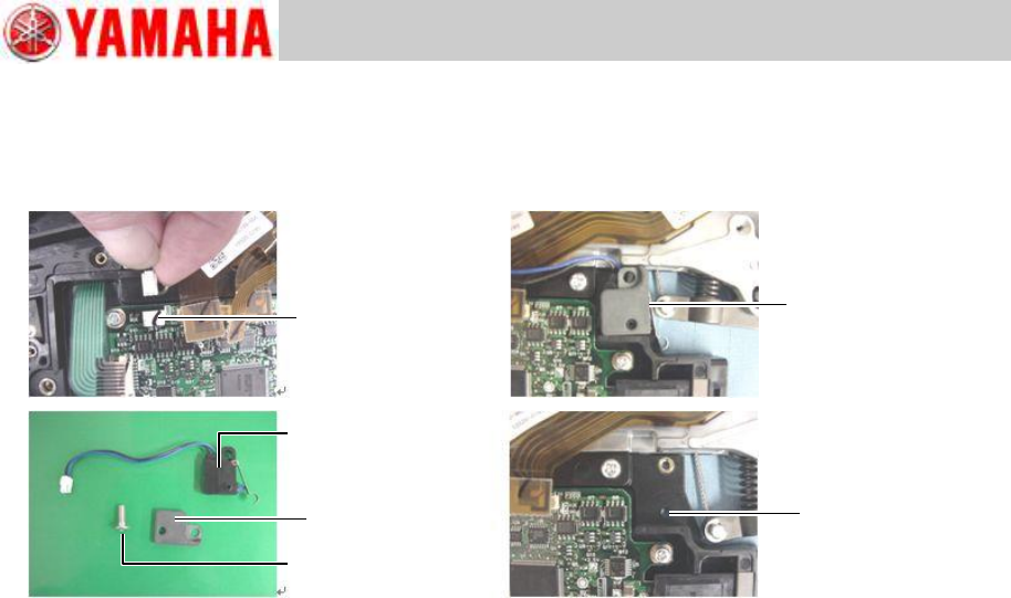
Step 7 Remove the mount screw of the limit switch using a 1.5 hex wrench.
Note
When removing the limit switch from the EL box, hold the unclamp lever so that limit switch is
not interfered.
Connector
Unclamped
Limit switch
Screw
Nut plate
EL box
positioning hole
Trained Customers
Service Information
18/27
SI1304003E-000 = 8mm ZS feeder maintenance procedures 1
2.10.2 Install the limit switch
Step 1 In an unclamped condition, insert the protruded part of the limit switch in the
positioning hole of the EL box.
Step 2 Fit the nut plate on the limit switch so that the limit switch’s protruded part is inserted
in the nut plate’s hole. Then fasten the limit switch with a screw using a 1.5 hex
wrench.
Apply Loctite 241 on the screw and tighten it to 30Ncm.
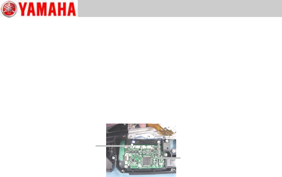
Step 3 Connect the limit switch to the feeder board assy at its connector.
Route the limit switch harness over the mount screw of the EL box.
Note
Jiggle the harness gently to check if the harness is securely connected.
Step 4 Place the cable cover on the EL box. Then install the earth cable of the peel motor on
the feeder body with a screw using a Phillips screwdriver (No.1).
Tightening torque of the mount screw is 40Ncm.
Note
The cable cover must be placed on the correct position to avoid its interference with mount
holes of the feeder side cover and others.
Step 5 Connect the harnesses from the feed motor, ABS board and peel motor to the feeder
board assy at respective connectors.
Step 6 Install the feeder side cover referring to “2.4 Replace the feeder side cover”, step 2.
Step 7 Install the EL box cover referring to “2.3 Replace the EL box cover”, step 2.
Note
You can check the operation status of the limit switch on the machine application.
Connect
or
EL box mount screw
Trained Customers
Service Information
19/27
SI1304003E-000 = 8mm ZS feeder maintenance procedures 1
2.11 Replace the EL box
2.11.1 Remove the EL box
Step 1 Remove the EL box cover referring to “2.3 Replace the EL box cover”, step 1.
Step 2 Disconnect the harnesses from the feeder board assy at respective connectors.
The harnesses are connected to the feed motor, ABS board, peel motor, limit switch,
operation switch and splice sensor (optional).
Step 3 Remove the screw fastening the earth cable of the peel motor using a Phillips
screwdriver (No.1).
Step 4 Remove the feeder side cover referring to “2.4 Replace the feeder side cover”,
step 1.
Step 5 Remove the cable cover.
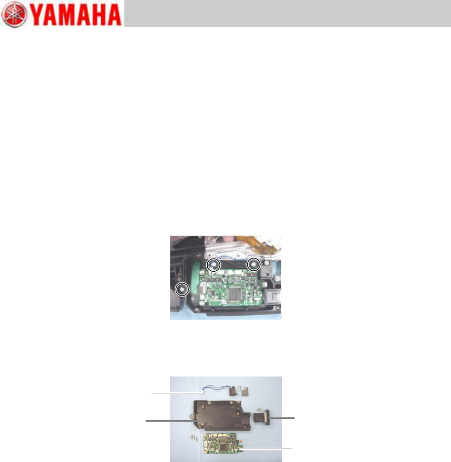
Step 6 Remove the EL box by removing its three screws using a Phillips screwdriver (No.2).
Step 7 Remove the two screws fastening the connector to the machine and the three screws
fastening the feeder board assy using a Phillips screwdriver (No.1).
Step 8 Remove the mount screw of the limit switch using a 1.5 hex wrench.
Limit switch
EL box
Connector
Feeder board assy