_482615_RE1304003 8mm ZS feeder maint.pdf - 第4页
Trained Customers Service Information 4/ 27 SI 1304003E- 00 0 = 8mm ZS feeder maintenance procedures 1 2 Replacement of faulty p arts (no adjustment is required af ter replac ement) 2.1 Replace the reel holder bracket St…
Trained Customers
Service Information
3/27
SI1304003E-000 = 8mm ZS feeder maintenance procedures 1
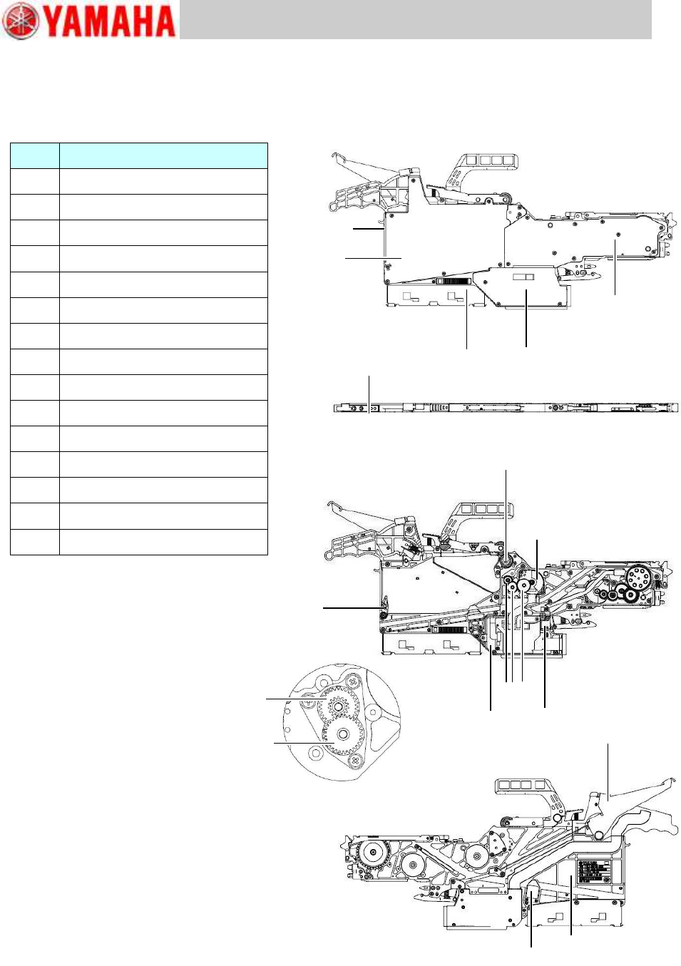
1 Required tools and replacement parts identification
YAMAHA standard tools
NSL grease
No.
Parts to replace
2-1
Reel holder bracket
2-2
Top tape box cover
2-3
EL box cover
2-4
Feeder side cover
2-5
Cutter
2-6
Tail cover
2-7
Operation switch
2-8
Unclamp lever
2-9
Top tape box
2-10
Limit switch
2-11
EL box
2-12
P/O1 roller and P4, P5 idle gears
2-13
P1, P2, P3 idle gears
2-14
Peel motor
2-15
Splice sensor (option)
2-1
2-2
2-3
2-4
2-6
2-7
2-8
2-9
2-15
2-12
2-12
2-5
2-12
2-10
2-11
2-13
2-14
Trained Customers
Service Information
4/27
SI1304003E-000 = 8mm ZS feeder maintenance procedures 1
2 Replacement of faulty parts (no adjustment is required after replacement)
2.1 Replace the reel holder bracket
Step 1 Remove the reel holder bracket from the feeder by removing the bracket’s three screws
using a Phillips screwdriver (No.1).
Step 2 Install the new reel holder bracket on the feeder with the screws removed in step 1. Use
the Phillips screwdriver (No.1) and tighten the screws to 40Ncm.
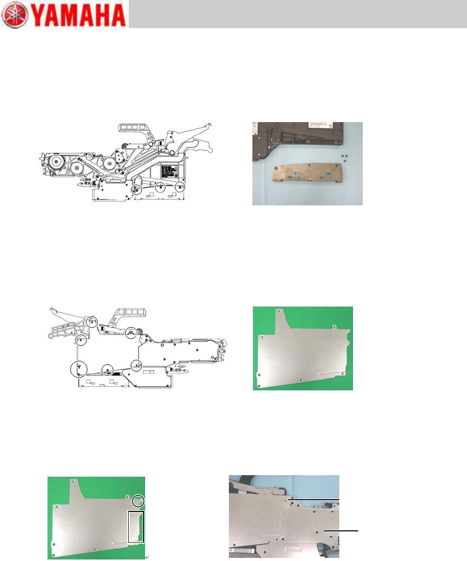
2.2 Replace the top tape box cover
Step 1 Remove the top tape box cover from the feeder by removing the cover’s seven screws
using a Phillips screwdriver (No.1).
Step 2 Install the new top tape box cover on the feeder with the screws removed in step 1. Use
the Phillips screwdriver (No.1) and tighten the screws to 40Ncm.
Note
When setting a top tape box cover, portions shown in below left figure get under the idle gear
2 cover (COVER, IDLE GEAR 2) and the feeder side cover (COVER, FEEDER SIDE 1).
Feeder side cover
Idle gear 2 cover
Trained Customers
Service Information
5/27
SI1304003E-000 = 8mm ZS feeder maintenance procedures 1
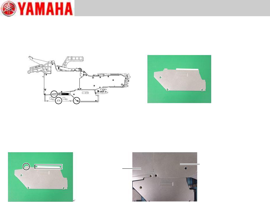
2.3 Replace the EL box cover
Step 1 Remove the EL box cover from the feeder by removing the cover’s three screws using
a Phillips screwdriver (No.1).
Step 2 Install the new EL box cover on the EL box with the screws removed in step 1. Use the
Phillips screwdriver (No.1) and tighten the screws to 40Ncm.
Note
When setting an EL box cover, portions shown in below left figure get under the feeder side
cover (COVER, FEEDER SIDE 1) and the top tape box cover (COVER, TOP TAPE BOX).
Note
The EL box cover of an 8mm wide feeder has a white sticker on its area which gets under the
feeder side cover
Feeder side cover
Top tape box cover