_482615_RE1304003 8mm ZS feeder maint.pdf - 第13页
Trained Customers Service Information 13 / 27 SI 1304003E- 00 0 = 8mm ZS feeder maintenance procedures 1 2.8.2 Install the uncla mp lever For inform ation about the unclam p wire rel ated parts, s ee “ ZS FEEDER User&apo…
Trained Customers
Service Information
12/27
SI1304003E-000 = 8mm ZS feeder maintenance procedures 1
2.8 Replace the unclamp lever
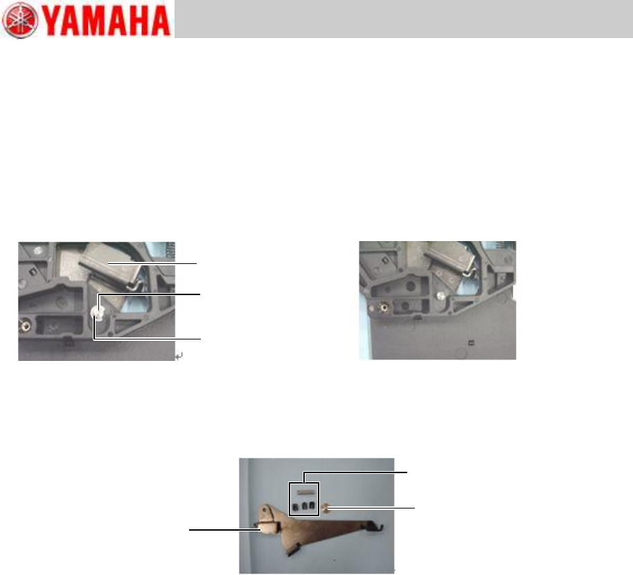
2.8.1 Remove the unclamp lever
Step 1 Remove the tail cover assy referring to “2.2 Replace the top tape box cover”, step 1.
Step 2 Remove the E-ring on the shaft where the unclamp lever is installed using a flat-blade
precision screwdriver.
Note
Take care not to lose the E-ring in its removal work. The E-ring is easy to drop and become
misplaced.
Step 3 Remove the shaft and the unclamp lever from the top tape box.
Note
The unclamp lever incorporates small parts related to the unclamp wire. Take care not to
lose the small parts in this step.
E-ring
Unclamp lever
Shaft
Unclamp lever
Shaft
Unclamp wire related parts
Trained Customers
Service Information
13/27
SI1304003E-000 = 8mm ZS feeder maintenance procedures 1
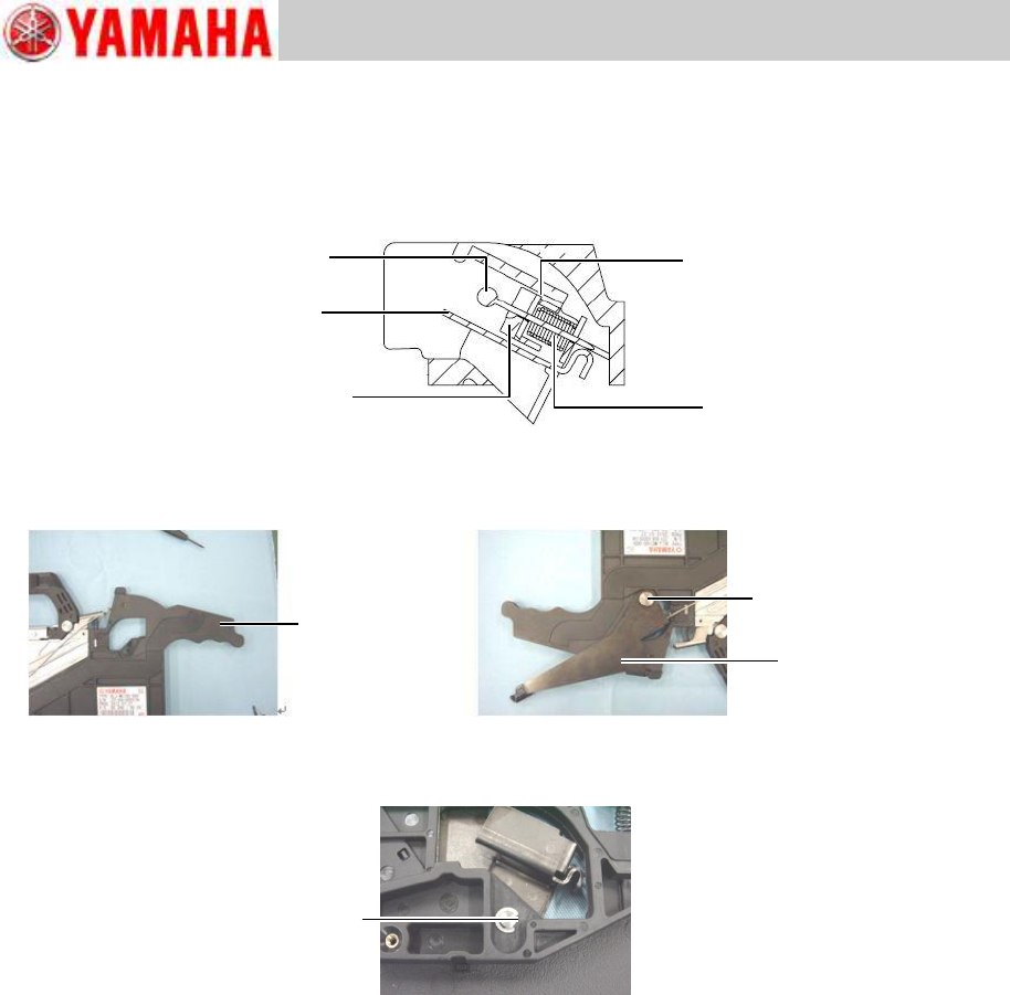
2.8.2 Install the unclamp lever
For information about the unclamp wire related parts, see “ZS FEEDER User's Manual”,
chapter 2 replacing parts.
Step 1 Install the unclamp wire related parts on the unclamp lever.
Step 2 Set the unclamp lever and its shaft on the top tape box
Step 3 Set the E-ring in the shaft’s groove with the E-ring’s flat side facing upward. Then
install the E-ring using the needle-nose pliers.
Step 4 Install the top tape box cover referring to “2.2 Replace the top tape box cover”,
step 2.
Unclamp wire
Unclamp lever
Tension spacer 1
Tension spacer 2
Tension spring
Top tape box
Shaft
Unclamp lever
E-ring’s flat side
Trained Customers
Service Information
14/27
SI1304003E-000 = 8mm ZS feeder maintenance procedures 1
2.9 Replace the top tape box
2.9.1 Remove the top tape box
Step 1 Remove the tail cover assy referring to “2.2 Replace the top tape box cover”, step 1.
Step 2 Remove the EL box cover assy referring to “2.3 Replace the EL box cover”, step 1.
Step 3 Remove the operation switch referring to “2.7.1 Remove the operation switch”.
Step 4 Remove the unclamp lever referring to “2.8.1 Remove the unclamp lever”.
Step 5 If the feeder is equipped with an optional splice sensor, remove the sensor referring to
“2.15.1 Remove the splice sensor”.
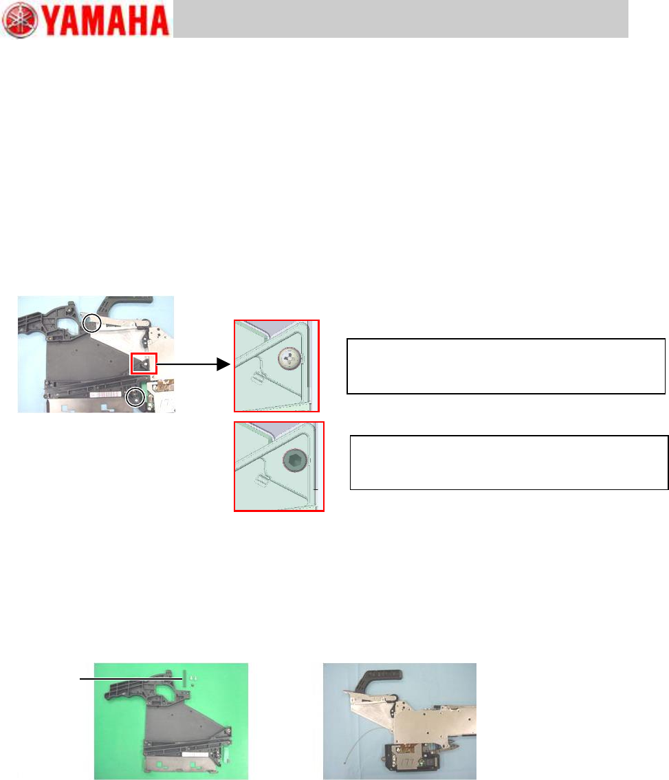
Step 6 Remove the three screws that fasten the top tape box to the feeder body and to the EL
box using a Phillips screwdriver (No.2).
Note
Take care not to lose the spring of the P/O lever assy that comes off in the above procedure.
Note
The operation switch and the serial plate cannot be reused. Make sure to use new ones
when the top tape box is replaced.
Note
Let us know the serial number of the feeder whose top tape box is to be replaced when
placing an order for a serial plate.
For feeder serial No.ZSY-0018166A or earlier
The same screw used in other positions (98502-03006
SCREW,PAN HEAD) is used.
For feeder serial No.ZSY-0018167A or later
Precoated screw (KHJ-MC11T-00 BOLT,LOCK S/H) is
used.
Spring