_482615_RE1304003 8mm ZS feeder maint.pdf - 第16页
Trained Customers Service Information 16 / 27 SI 1304003E- 00 0 = 8mm ZS feeder maintenance procedures 1 2.10 Replace the limit switch 2.10.1 Remov e the limit switch Step 1 Remove the EL box cover referring t o “ 2. 3 R…
Trained Customers
Service Information
15/27
SI1304003E-000 = 8mm ZS feeder maintenance procedures 1
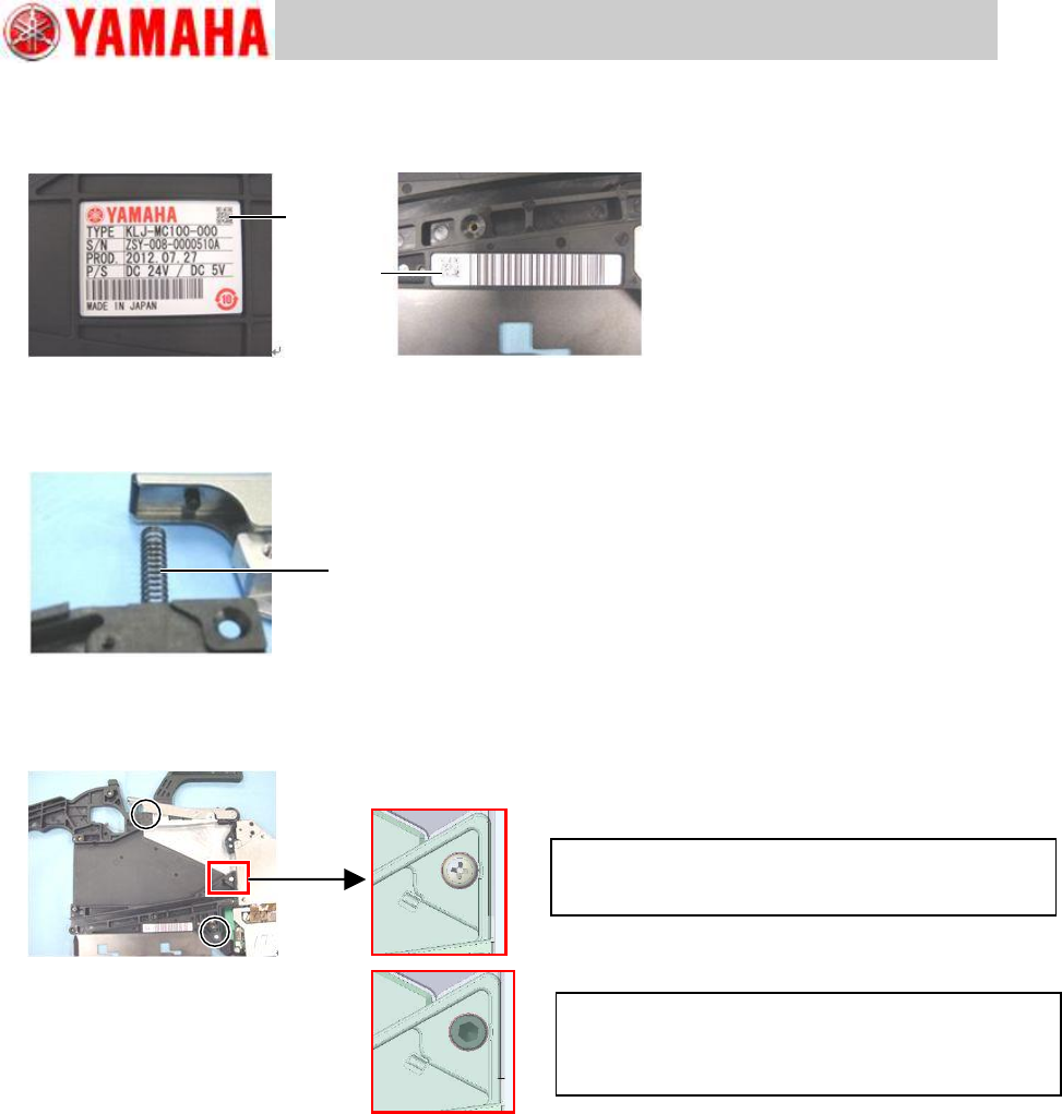
2.9.2 Install the top tape box
Step 1 Attach the new serial plate and barcode to the new top tape box.
Step 2 Insert one end of the P/O lever spring into the hole on the top tape box, and set the
other end to the protruding portion of the P/O lever assy while adjusting the position to
set the top tape box to the feeder body.
Step 3 Tighten two screws that fasten the top tape box to the feeder body, and one screw that
fastens the top tape box to the EL box using a Phillips screwdriver (No.2). Tightening
torque is 75Ncm.
Note
If the top tape box warps by screwing it onto the feeder body, it is recommended to replace
the existing regular screws with precoated screws (KHJ-MC11T-00 BOLT,LOCK S/H). When
you use precoated screws, tighten the screw to specified torque, then screw out by 90
degrees.
Step 4 Install the operation switch referring to “2.7.2 Install the operation switch”.
Step 5 Install the top tape box cover referring to “2.2 Replace the top tape box cover”, step 2.
Step 6 Install the tail cover assy referring to “2.6.2 Install the tail cover assy”.
Step 7 If the feeder is equipped with optional splice sensor, install the sensor referring to
“2.15.2 Install the splice sensor”.
Step 8 After replacing the top tape box, set the tape feeder to a feeder station and press the
operation switch to check if it works properly.
For feeder serial No.ZSY-0018166A or earlier
Use the same screw used in other positions
(98502-03006 SCREW,PAN HEAD).
For feeder serial No.ZSY-0018167A or later
Use precoated screw (KHJ-MC11T-00 BOLT,LOCK
S/H) is used. Tighten the screw once and then screw
out by 90 degrees.
Serial plate
Barcode
Spring
Trained Customers
Service Information
16/27
SI1304003E-000 = 8mm ZS feeder maintenance procedures 1
2.10 Replace the limit switch
2.10.1 Remove the limit switch
Step 1 Remove the EL box cover referring to “2.3 Replace the EL box cover”, step 1.
Step 2 Remove the feeder side cover referring to “2.4 Replace the feeder side cover”,
step 1.
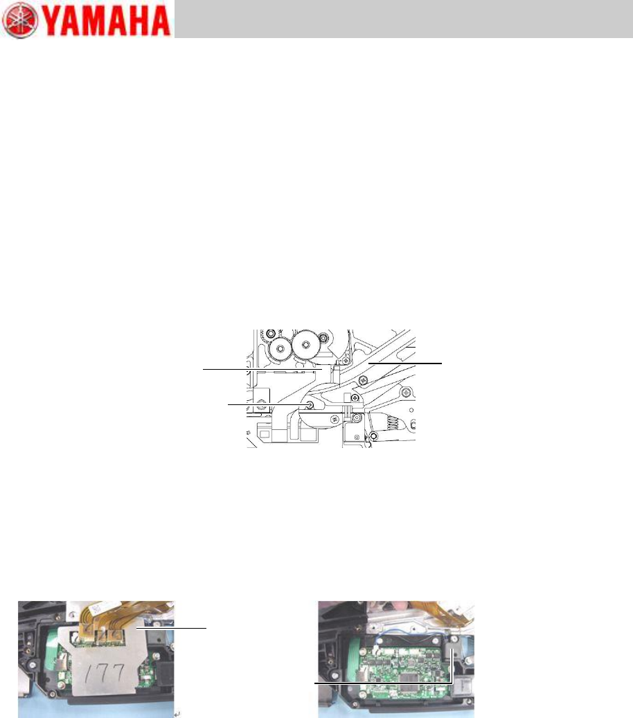
Step 3 Disconnect the harnesses from the feed motor, ABS board and peel motor to the
feeder board assy at respective connectors.
Step 4 Remove the earth cable of the peel motor by removing its mount screw using a Phillips
screwdriver (No.1).
Note
The earth cable mount screw is under the ABS board harness. Lift the harness and remove
the mount screw.
Step 5 Remove the cable cover shown in the below left figure.
Lift the feed motor harness, ABS board harness and peel motor harness and then remove the
cable cover.
Note
As the cable cover adheres lightly to the QFP on the feeder board assy, be careful not to
bend the cable cover in its removal. If the heat conduction film is stuck to the QFP, remove
the film and re-attach it to the cable cover.
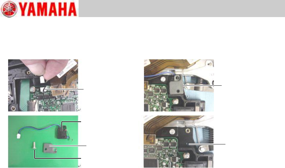
Step 6 Disconnect the limit switch at its connector to the feeder board assy.
Peel motor harness
Earth cable mount screw
ABS board harness
Cable cover
Limit switch
Trained Customers
Service Information
17/27
SI1304003E-000 = 8mm ZS feeder maintenance procedures 1
Step 7 Remove the mount screw of the limit switch using a 1.5 hex wrench.
Note
When removing the limit switch from the EL box, hold the unclamp lever so that limit switch is
not interfered.
Connector
Unclamped
Limit switch
Screw
Nut plate
EL box
positioning hole