_482615_RE1304003 8mm ZS feeder maint.pdf - 第23页
Trained Customers Service Information 23 / 27 SI 1304003E- 00 0 = 8mm ZS feeder maintenance procedures 1 2.13 Replace the P1, P2 and P3 idle gears Note Each of those gear s can be replaced separatel y; the y do not need …
Trained Customers
Service Information
22/27
SI1304003E-000 = 8mm ZS feeder maintenance procedures 1
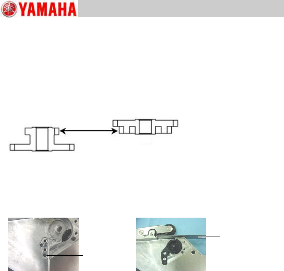
2.12.2 Install the P/O1 roller, P4 and P5 idle gears
Apply a tiny amount of NSK NSL grease at where relevant positioning pins and gears come in
contact.
Note
Do not apply grease to the gear section. If the gear is contaminated with grease, wipe the
gear clean.
Step 1 Set the Idle P4 gear to the shaft close to the EL box so that the side with more teeth
faces down.
Step 2 Set the Idle P5 gear to the upper shaft so that the side with fewer teeth faces down, and
then rotate the gears slightly in order to mesh them properly.
Step 3 Fit the “Idle gear 1” cover into the holes of the positioning pins, and fasten the cover
with three screws using a Phillips screwdriver (No.1). Tightening torque is 40Ncm.
Step 4 Insert a scale between the P/O lever assy gear and the feeder body to install the P/O
tooth 1 block and P/O 1 roller.
Note
Insert the claw of the P/O tooth 1 block into the groove of the P/O 1 roller, then set them
together little by little to the feeder body.
Fasten the P/O Tooth 1 block to the feeder body with two screws using a hex wrench (Size 2).
Tightening torque is 20Ncm.
Step 5 Remove the scale and rotate the P/O lever gear to check that the gear rotates
smoothly.
Step 6 Fit the “Idle gear 2” cover into the holes of the positioning pins, and fasten the cover
with two screws using a Phillips screwdriver (No.1). Tightening torque is 40Ncm.
Step 7 Install the top tape box cover to the feeder body referring to “2.2 Replace the top
tape box cover”, step 2.
P4
P5
Positioning hole
Scale
Trained Customers
Service Information
23/27
SI1304003E-000 = 8mm ZS feeder maintenance procedures 1
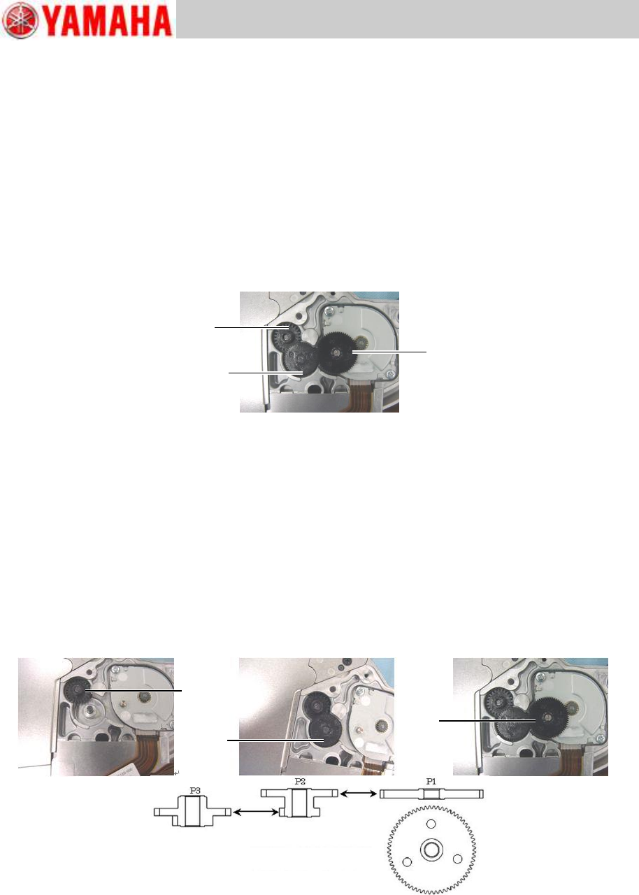
2.13 Replace the P1, P2 and P3 idle gears
Note
Each of those gears can be replaced separately; they do not need to be replaced as a set.
2.13.1 Remove the P1, P2 and P3 idle gears
Step 1 Remove the feeder side cover referring to “2.4 Replace the feeder side cover”,
step 1. Apply a tiny amount of NSK NSL grease at where relevant positioning pins and
gears come in contact.
Note
Do not apply grease to the gear section. If the gear is contaminated with grease, wipe the
gear clean.
Step 2 Remove the P1, P2 and P3 idle gears from respective shafts.
2.13.2 Install the P1, P2 and P3 idle gears
Apply a tiny amount of NSK NSL grease at where relevant positioning pins and gears come in
contact.
Note
Do not apply grease to the gear section. If the gear is contaminated with grease, wipe the
gear clean.
Step 1 Set the gears to the shaft in order of the P3 idle gear, P2 idle gear and P1 idle gear
Note
Set the P1 idle gear so that its three recessed areas face upward.
Step 2 Rotate the gears slightly in order to mesh them the same way as the P4 and P5 idle
gears.
Step 3 Rotate the P1 idle gear to check that the gears up to the P/O lever gear rotate smoothly.
Step 4 Install the feeder side cover referring to “2.4 Replace the feeder side cover”, step 2.
P2
P3
P1
P3
P2
P1
Trained Customers
Service Information
24/27
SI1304003E-000 = 8mm ZS feeder maintenance procedures 1
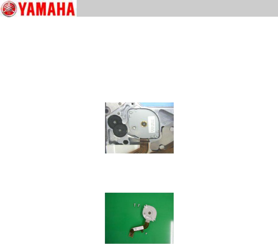
2.14 Replace the peel motor
2.14.1 Remove the peel motor
Step 1 Remove the EL box cover referring to “2.3 Replace the EL box cover”, step 1.
Step 2 Remove the feeder side cover referring to “2.4 Replace the feeder side cover”,
step 1. Apply a tiny amount of NSK NSL grease at where relevant positioning pins and
gears come in contact.
Step 3 Disconnect the feed motor harness from the feeder board assy at its connector.
Step 4 Remove the P1 idle gear upward from the feeder body.
Step 5 Remove the screw fastening the peel motor harness using a Phillips screwdriver
(No.1).
Step 6 Remove the two screws fastening the peel motor using a Phillips screwdriver (No.1)
and remove the peel motor upward from the feeder body.