00192216-01.pdf - 第38页
1 Nachrüstanleitung für Option Keram iksubstrat-Zentrierung SIPL ACE 80 S-20 / S-23HM/ F4 / F4-6 / F 5 1.6 Anhang: Kabel und Schaltpläne Umsetzplatine Ausgabe 04/2000 38 q
SIPLACE 80 S-20 / S-23HM/ F4 / F4-6 / F5 1 Nachrüstanleitung für Option Keramiksubstrat-Zentrierung
Ausgabe 04/2000 1.6 Anhang: Kabel und Schaltpläne Umsetzplatine
37
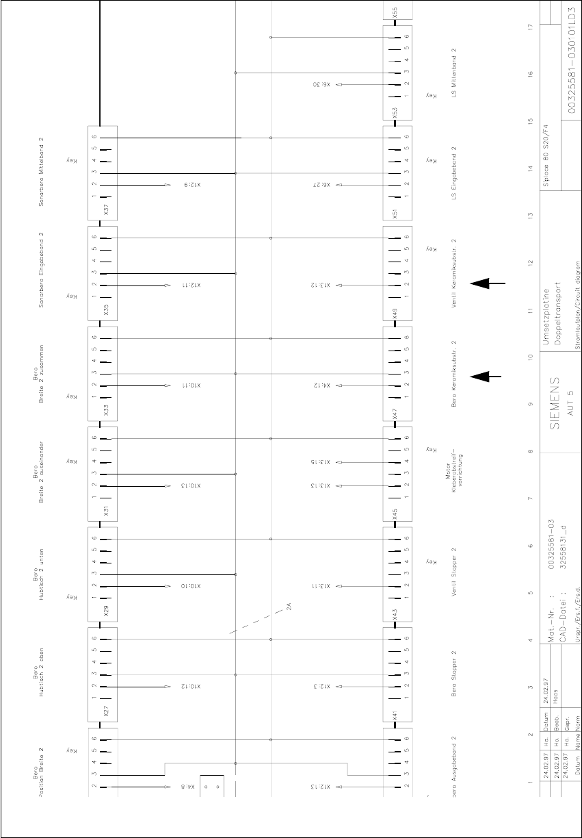
Abb. 1.6.5 Umsetzplatine LP-Transportsteuerung (SIPLACE 80 S20/F4)
1 Nachrüstanleitung für Option Keramiksubstrat-Zentrierung SIPLACE 80 S-20 / S-23HM/ F4 / F4-6 / F5
1.6 Anhang: Kabel und Schaltpläne Umsetzplatine Ausgabe 04/2000
38
q

SIPLACE 80 S-20 / S-23HM/ F4 / F4-6 / F5 2 Retrofitting Instructions for Ceramic Substrate Centering Unit (Optional)
04/2000 Issue 2.1 Overview
39
5HWURILWWLQJ,QVWUXFWLRQVIRU&HUDPLF
6XEVWUDWH&HQWH ULQJ8QLW2SWLRQDO
2Y HUY LHZ
These instructions contain a description of the optional ceramic substrate centering unit on
SIPLACE 80 S-20, S-23 HM, F4 and F4-6, F5.
These machines possess the new PCB conveyor with PCB conveyor control. For that reason -
after the lifting table plate is removed - the solenoid valve and inductive proximity switch of the
option are electrically connected to the conversion PCB for the PCB conveyor control (see Sec-
tion 2.6).
The setup of the placement conveyor modules must be amended to use the ceramic substrate
centering unit.
.
The 2 fastening and centering holes used to mount the X-centering unit have already been made
in the lifting table plate.
The optional ceramic substrate centering unit is always installed in both PCB conveyors when-
ever machines with dual conveyors are involved. For the substrate centering unit, a 2nd solenoid
valve is mounted on the back of the compressed air unit (see Fig. 2.4.4).
NOTE:
For machines with the optional "PCB conveyor, left", install the designated retrofit kit ceramic sub-
strate centering unit for PCB conveyor, LH, item no. 00116914-01.
This retrofitting is not described here but can be performed in a like manner.