00192216-01.pdf - 第57页
SIPLACE 80 S-20 / S-23HM/ F4 / F4-6 / F5 2 Retrof itting Instructions for Ceramic S ubstrate Centering Unit (Optional) 04/2000 Issue 2.4 Sequence of Retrofitting 57 ,QVWDOOLQJWKH6OL GH8QLWIRUWKH;'LUHFWL…
2 Retrofitting Instructions for Ceramic Substrate Centering Unit (Optional) SIPLACE 80 S-20 / S-23HM/ F4 / F4-6 / F5
2.4 Sequence of Retrofitting 04/2000 Issue
56
Å Tip the compressed air unit back up and fasten it to the machine frame on the RH side with 2
socket hex head cap screws.
Å Fasten the cables to the pedestals with cable ties and stow the extra lengths of cable in the
cable pit.
Å To ascertain the unused length of proximity switch cable that is required, hold the centering
unit at approximately the point on the stationary conveyor side at which the centering unit
will eventually be installed.
Å Make certain that the plug-and-socket connections are not under tension.
Å Install the cover on the cable pit and the conveyor control.

SIPLACE 80 S-20 / S-23HM/ F4 / F4-6 / F5 2 Retrofitting Instructions for Ceramic Substrate Centering Unit (Optional)
04/2000 Issue 2.4 Sequence of Retrofitting
57
,QVWDOOLQJWKH6OLGH8QLWIRUWKH;'LUHFWLRQ5HWURILW.LW
Å Loosen the screws on the slide unit that fasten the body to the support rail (2 socket hex head
cap screws M4, see Fig. 2.4.7 -> 2, 3).
Å Lift off body with slide unit.
Å Use a 2.5 mm punch.
Drive the 2 parallel pins 3M5x10 DIN 6325 so far into the holes in the centering unit (see Fig.
2.4.7 -> 4) that they project about 4 mm on the bottom of the support rail.
-> The pins are not included in the retrofit kit (see Section 2.3.2) !
NOTE:The centering holes and the thread to fasten the slide unit are already including in the lifting
table plate.
Å Install the support rail with the centering pins into the lifting table plate and secure the screws
holding the support rail ((2 screws: M4 x 30, see Fig. 2.4.7 -> 5).
-> The screws are not included in the retrofit kit (see Section 2.3.2) !
Å Screw the body back on the support rail (2 socket hex head cap screws M4).
Å If you have not already done so, adjust the holder on the slide unit to the substrate size to be
processed thereafter (see Fig. 2.4.8).
2 Retrofitting Instructions for Ceramic Substrate Centering Unit (Optional) SIPLACE 80 S-20 / S-23HM/ F4 / F4-6 / F5
2.4 Sequence of Retrofitting 04/2000 Issue
58
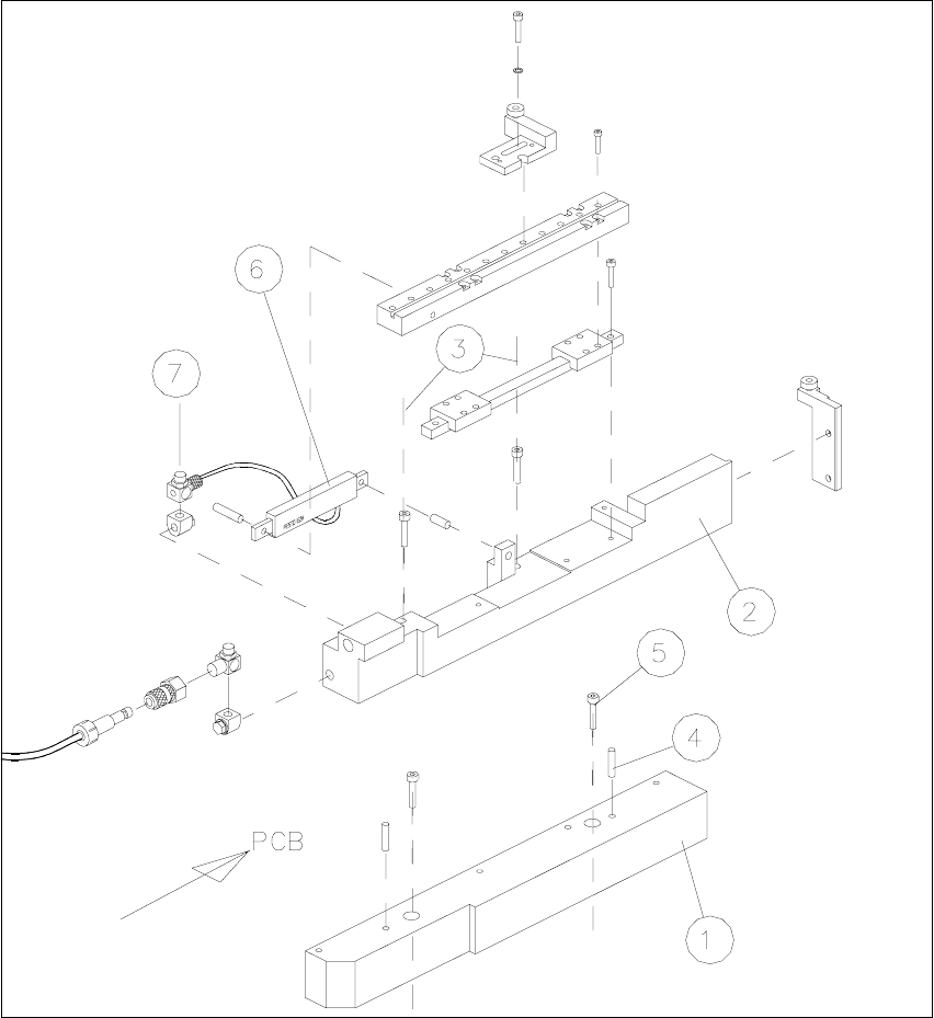
Fig. 2.4.7 Installing the X-Centering Unit on the Lifting Table Plate
1. Bottom part of slide unit
2. Body with slide unit
3. Loosen the screws fastening the body (2 socket hex head cap screws M4)
4. 2 parallel pins 3M5x10 DIN 6325 (for installation on the lifting table plate)
5. 2 socket hex head cap screws M4 x 30 (for installation on the lifting table plate)
6. Flat type compressed air cylinder
7. Throttle valve (opening speed)