00192216-01.pdf - 第46页
2 Retrofitting Instructions for Ceramic Substrate Centering Unit (O ptional) SIPLACE 80 S-20 / S-23HM/ F4 / F4-6 / F5 2.4 Sequence of Retrofitt ing 04/2000 Issue 46 5HPRY LQJW KH3&%+ROGGRZ QV DQG3&%*X…

SIPLACE 80 S-20 / S-23HM/ F4 / F4-6 / F5 2 Retrofitting Instructions for Ceramic Substrate Centering Unit (Optional)
04/2000 Issue 2.4 Sequence of Retrofitting
45
Where applicable, dismantle the component table (1 or 2).
Å Remove the tape waste chute (just hooked in at F5).
-> This makes the PCB conveyor easier to access.
Å At SIPLACE 80 F4 / F4-6/F5:
Å Lift out the nozzle changer for the IC head.
Å Lift off the top-mounted attachment of flip-chip camera and IC camera.
Å For the time being, put these attachments and the nozzle changer down in a secure place.
Å Conscientiously cover the area of the camera and the coplanarity sensor, e.g., with a large,
clean cloth or carton.
5HPRYLQJWKH/LIWLQJ7DEOH
NOTE:
The lifting table plate must be removed, for example, in order to exchange the holddown device
from retroft kit and to make the electrical connection of the centering unit at the PCB conveyor
control.
The PCB conveyor is already set to maximum width.
Å Move the Y-gantry / Y-gantries into the area outside the PCB conveyor.
Å Remove the reinforcing rail from the movable conveyor side (inside).
Å In the pertinent conveyor area, on the fixed
DQG
the movable conveyor side, slightly loosen the
M3 setscrew on the ball bearing of each rocking lever on LH and RH (see Fig. 2.4.1 -> 2 to 5).
Å Being careful not to misplace the setscrew and the spacer disk, remove the two ball bearings
and the spacer disk under them from each rocking lever).
WARNING
During the subsequent lifting of the lifting table plate there is a risk of body members being
pinched, crushed or cut off, e.g., between the outer edges of the lifting table plate and the con-
veyor assemblies. Wear strong protective gloves.
Å Holding the lifting table plate with both hands, lift it up vertically.
Å Make certain the lifting table is not tilted while being lifted.
Å Place the lifting table plate upside down on a clean, flat surface.
2 Retrofitting Instructions for Ceramic Substrate Centering Unit (Optional) SIPLACE 80 S-20 / S-23HM/ F4 / F4-6 / F5
2.4 Sequence of Retrofitting 04/2000 Issue
46
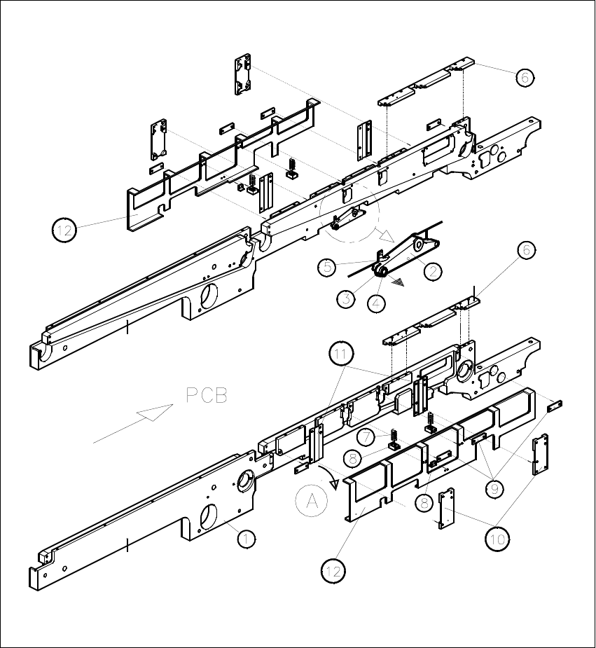
5HPRYLQJWKH3&%+ROGGRZ QV DQG3&%*XLGH5DLOV
Fig. 2.4.1 Removing the PCB Holddowns and PCB Guide Rails
SIPLACE 80 S-20 / S-23HM/ F4 / F4-6 / F5 2 Retrofitting Instructions for Ceramic Substrate Centering Unit (Optional)
04/2000 Issue 2.4 Sequence of Retrofitting
47
.H\WR)LJ
A) Direction of movement for removal of the holddown device (LH, RH)
8. Conveyor assembly, fixed conveyor side
9. Rocking lever for movable / fixed side: NOT TO REMOVE
10.Set screw M3 x 5
11.Ball bearing (remove to dismantle the lifting table plate)
12.Compression spring on rocking lever
13.PCB guide rails
14.Compression spring for holddown device
15.Retaining bracket (bracket)
16.DU strips (3 units)
17. Guide for holddown
18. Sliding strips (2 units) for holddown device
19. Holddown device (to remove)
Carry out the following steps on the fixed and movable conveyor side:
Å Remove the 3 DU strips (see Fig. 2.4.1 -> 9) and the two guides for the holddown devices (see
Fig. 2.4.1 -> 10 and 11) on the exterior of the conveyor.
To do so, undo and remove the M3 cross-slotted and hexagonal socket head cap screws.
Å Remove the guide rails on both conveyor sides (see Fig. 2.4.1 -> 6).
To do so, undo and remove the socket head cap screws M3.
Å During the subsequent removal of the holddowns make certain that the 2 compression springs
each (see Fig. 2.4.1 -> 7, 8) are not lost:
Å Fold the holddown device to the outside (direction of movement: see Fig. 2.4.1 -> A) and
take it off.
Å During the process, remove the compression spring from the retaining bracket: seeFig.
2.4.1 -> 7 and 8).