00192216-01.pdf - 第60页
2 Retrofitting Instructions for Ceramic Substrate Centering Unit (O ptional) SIPLACE 80 S-20 / S-23HM/ F4 / F4-6 / F5 2.4 Sequence of Retrofitt ing 04/2000 Issue 60 Fig. 2.4.8 Adjusting the S ubstrate Size

SIPLACE 80 S-20 / S-23HM/ F4 / F4-6 / F5 2 Retrofitting Instructions for Ceramic Substrate Centering Unit (Optional)
04/2000 Issue 2.4 Sequence of Retrofitting
59
6HWWLQJWKH2SHUD WLQJ'LVWDQFHRIWKH3UR[LPLW\ 6ZLWFK
Å Make certain that the operating surface of the inductive proximity switch is set 0.2 mm back
from the stop surface of the slide unit in the hole.
This precludes the possibility that the proximity switch might serve as a stop during the opening
movement and being damaged as a result.
Å If necessary, correct the position of the proximity switch (grub screw, size 1 Allen wrench).
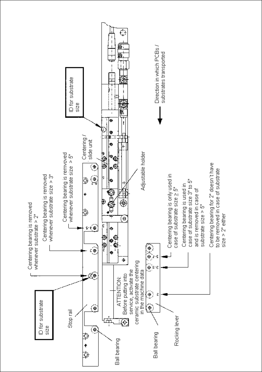
$GMXVWLQJWRWKH6XEVWUDWH6L]H
To ensure the 3-point contact of the substrate for the centering unit in the Y-direction, the ceramic
substrate centering unit has to be adjusted to the substrate size to be processed afterwards.
The thrust-piece holder and the long guide rail have to be removed to do this (see Fig. 2.4.3 -> 5,
10).
Å Adjust the arrangement of the ball bearings in the long guide rails and in the thrust-piece holder
to the substrate size, as shown in Fig. 2.4.8.
Å If necessary, use a punch (2.5 mm) to drive out the pertinent shaft including the ball bearings
(pressure seating).
NOTE
Carefully save the ball bearings that were removed, including the shaft, so that they will be again
be available for a change made back to a smaller substrate size.
Å If necessary, also adjust the holder on the "slide unit for X-direction) to the required substrate
size (see Fig. 2.4.8).
2 Retrofitting Instructions for Ceramic Substrate Centering Unit (Optional) SIPLACE 80 S-20 / S-23HM/ F4 / F4-6 / F5
2.4 Sequence of Retrofitting 04/2000 Issue
60
Fig. 2.4.8 Adjusting the Substrate Size

SIPLACE 80 S-20 / S-23HM/ F4 / F4-6 / F5 2 Retrofitting Instructions for Ceramic Substrate Centering Unit (Optional)
04/2000 Issue 2.4 Sequence of Retrofitting
61
,QVWDOOLQJWKH/LIWLQJ7DEOH&RQQH FWLQJWKH 6OLGH8QLW
WARNING OO
During the subsequent installation of the lifting table plate there is a risk of body members being
pinched, crushed or cut off, e.g., between the outer edges of the lifting table plate and the con-
veyor assemblies.
Å Make certain that the transmission lever on the pertinent lifting table motor is folded down on
the lifting curve.
Å Holding the lifting table with both hands, place it into the guiding tubes with the guide pillars
vertical.
Å Let the lifting table plate slowly side down.
Å Check whether the lifting table plate is
FRPSOHWHO\
seated on the lifting curve.
Å Install the pertinent ball bearing on each rocking lever (see Fig. 2.4.1 -> 2). While doing so, put
the spacer disk back in.
Å Make the plug-and-socket connection between the proximity switch on the "slide unit, X-direc-
tion" (see Fig. 2.4.3 -> 13).
Å Connect the pneumatic hose of each solenoid valve to the threaded hose connection of the
pertinent slide unit (see Fig. 2.4.3 -> 14).
Å Re-install the reinforcement strip on the movable conveyor side (inside).
,QVWDOOLQJ7RS0RXQW&DPHUD$WWDFKP1R]]OH&KDQJ&KDQJHRYHU7DEOHV
:3&
Å Remove all tools, etc., from the work area of the machine.
Å Move the gantry or gantries into the area over the PCB conveyor.
NOTE:
Be careful not to push the gantries together too much, otherwise the crash switch will be actuated
later when you turn the machine ON.
Å Remove the cover over the cameras carefully so that any parts, screws, etc. that may be lying
on it do not drop into the cameras.
Å Re-install the top-mounted camera attachments and the nozzle changer.
Å Re-install the waste chute.