00192216-01.pdf - 第49页
SIPLACE 80 S-20 / S-23HM/ F4 / F4-6 / F5 2 Retrof itting Instructions for Ceramic S ubstrate Centering Unit (Optional) 04/2000 Issue 2.4 Sequence of Retrofitting 49 Fig. 2.4.2 Assembly: Clamping Element with Rocker and…
2 Retrofitting Instructions for Ceramic Substrate Centering Unit (Optional) SIPLACE 80 S-20 / S-23HM/ F4 / F4-6 / F5
2.4 Sequence of Retrofitting 04/2000 Issue
48
,QVWDOOLQJWKH+ROGGRZQV<&HQWHULQJ8QLWDQG*XLGH3DUWV5HWURILWWLQJ.LW
Å First, adjust the following parts from the retrofitting kit to the substrate size that will be pro-
cessed afterwards, as described in Section 2.4.9:
– Centering unit (slide unit, X-direction)
– Thrust-piece holder
– "Guide rail, RH, assembly"
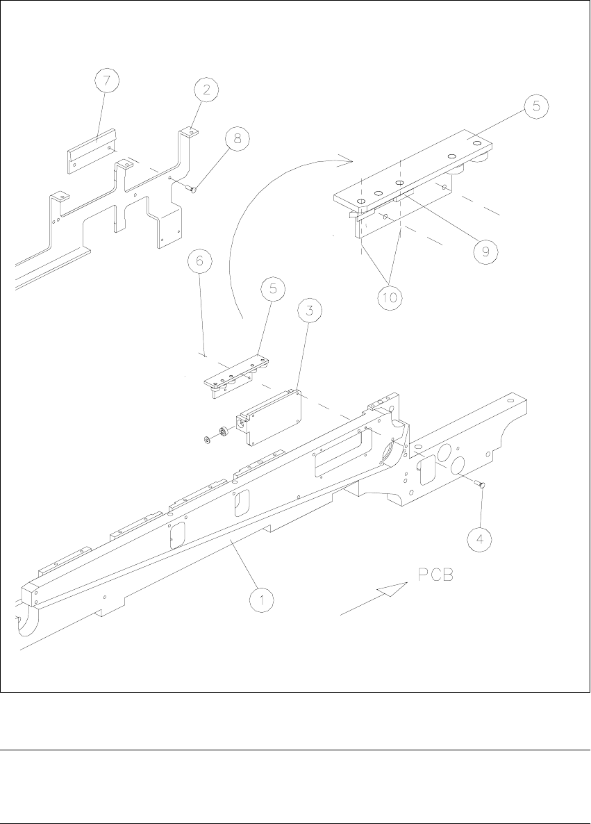
Å Using 4 countersunk screws M2 x 6, mount the Y-centering unit which consists of the clamping
element with rocker and thrust- piece holder (preassembled) on the rectangular cutout on the
movable conveyor side (see Fig. 2.4.2 -> 3, 4, 5, 6 ).
Å Exchange the compression spring(s) of the pertinent holddown (see Fig. 2.4.1 -> 7), if this is/
they are less than 32 mm long when not subjected to load -> item no. of the compression
spring: see Section 2.3.2.
Å In the reverse order to that described for removal in Section 2.4.3, install the pertinent hold-
down from the retrofitting kit, including the (if necessary, new) compression spring with retain-
ing bracket (support).
Key to Fig. 2.4.2 (RH):
A) Cable proximity switch -> to conversion PCB for PCB conveyor
B) Pneumatic hose -> to the solenoid valve on the back of the compressed air unit
1. Conveyor assembly, movable side
2. Holddown device, movable side *)
3. Clamping element with rocker, installed *) **)
4. Screws to fasten the clamping element: 4 countersunk screws M2 x 6 DIN965 *)
5. Thrust-piece holder (centering in Y-direction) *) **)
6. Screws to fasten the thrust-piece holder **)
7. Actuator for rocker *)
8. Screws to fasten the actuator for the rocker: 2 countersunk screws M2 x 6 *) **)
9. Green plastic rail *)
This is installed instead of ball bearing when the substrates are only centered in the Y-direction.
It is fastened to the thrust-piece holder with 2 countersunk screws M3 x 6 (from the bottom)
each with 2 hex nuts.
10. 2 countersunk screws M3 x 6 (screwed in from the bottom)
*) from retrofit kit
**) already included in the retrofit kit as an installed unit.
SIPLACE 80 S-20 / S-23HM/ F4 / F4-6 / F5 2 Retrofitting Instructions for Ceramic Substrate Centering Unit (Optional)
04/2000 Issue 2.4 Sequence of Retrofitting
49
Fig. 2.4.2 Assembly: Clamping Element with Rocker and Thrust-Piece Holder, Rocker Actuator
NOTE:
Do not screw the following substrate guide elements (roller rails) completely tight yet as the align-
ment of the roller rails will have to be adjusted in a later step.

2 Retrofitting Instructions for Ceramic Substrate Centering Unit (Optional) SIPLACE 80 S-20 / S-23HM/ F4 / F4-6 / F5
2.4 Sequence of Retrofitting 04/2000 Issue
50
Å Install the (substrate) "Guide, short" and the (substrate) rail on the movable conveyor side (see
Fig. 2.4.3 -> 7, 8, 9):
-> Use the 2 socket hex head cap screws M3 x 8 previously removed to do so.
Å Install the (substrate) "Guide rail, RH" on the stationary conveyor side (see Fig. 2.4.3):
-> Use the 4 socket hex head cap screws M3 x 8 previously removed.
NOTE:
The 2 connecting rails included in the retrofit kit for the holddowns are not installed because they
are only required for reinstallation on the PCB centering unit (see Section 2.5).
Retain all of the parts not currently used as well as the 2 connecting rails, PCB guide rails and
disassembled ball bearings with shaft and screws so that they will be available for reinstallation
on the PCB conveyor or in case of a change in the substrate size.
Key to Fig. 2.4.3:
1. Conveyor assembly, fixed side
2. Holddown device for fixed side *)
3. Holddown device for movable side *)
4. Clamping element with rocker, installed *)
5. Thrust-piece holder (centering in Y-direction) *)
6. Rocker actuator *)
7. Guide, short (with rollers) *)
8. Rail (with rollers) *)
9. Fasteners: 2 socket hex head cap screws M3 x 8 *) each
10.Guide rail assembly, RH (long, with rollers) *)
11.Fasteners: 4 socket hex head cap screws M3 x 8 *)
12.inductive proximity switch for ceramic substrate centering unit *)
13.Cable, proximity switch, ceramic substrate centering unit *)
14.PCB holddown bracket (on stationary and movable side) *)
required only for reinstallation on PCB centering unit
15.Fasteners: 6 socket hex head cap screws M3 x 6 *) each
required only for reinstallation on PCB centering unit
*) included in the retrofit kit