00192216-01.pdf - 第66页
2 Retrofitting Instructions for Ceramic Substrate Centering Unit (O ptional) SIPLACE 80 S-20 / S-23HM/ F4 / F4-6 / F5 2.6 Appendix: Cables and Circuit Drawings, Conversi on PCB 04/2000 Issue 66 Fig. 2.6.2 Cable for Pro…
SIPLACE 80 S-20 / S-23HM/ F4 / F4-6 / F5 2 Retrofitting Instructions for Ceramic Substrate Centering Unit (Optional)
04/2000 Issue 2.6 Appendix: Cables and Circuit Drawings, Conversion PCB
65
$SSHQGL[ &DEOH VDQG&LUFXLW' UDZLQJV&RQYHU
VLRQ3&%
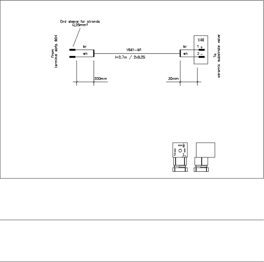
Fig. 2.6.1 Cable of Solenoid Vavle for SIPLACE 80 F4/F4-6/F5 and S20/S23HM
NOTE:
The connector sleeves of the solenoid valve and proximity switch cable are furnished for
the installation on the SIPLACE S-15 / F3. In all other instances, you must remove them and attach
AMPMODU contacts instead (details: see Section 2.4.5).
2 Retrofitting Instructions for Ceramic Substrate Centering Unit (Optional) SIPLACE 80 S-20 / S-23HM/ F4 / F4-6 / F5
2.6 Appendix: Cables and Circuit Drawings, Conversion PCB 04/2000 Issue
66
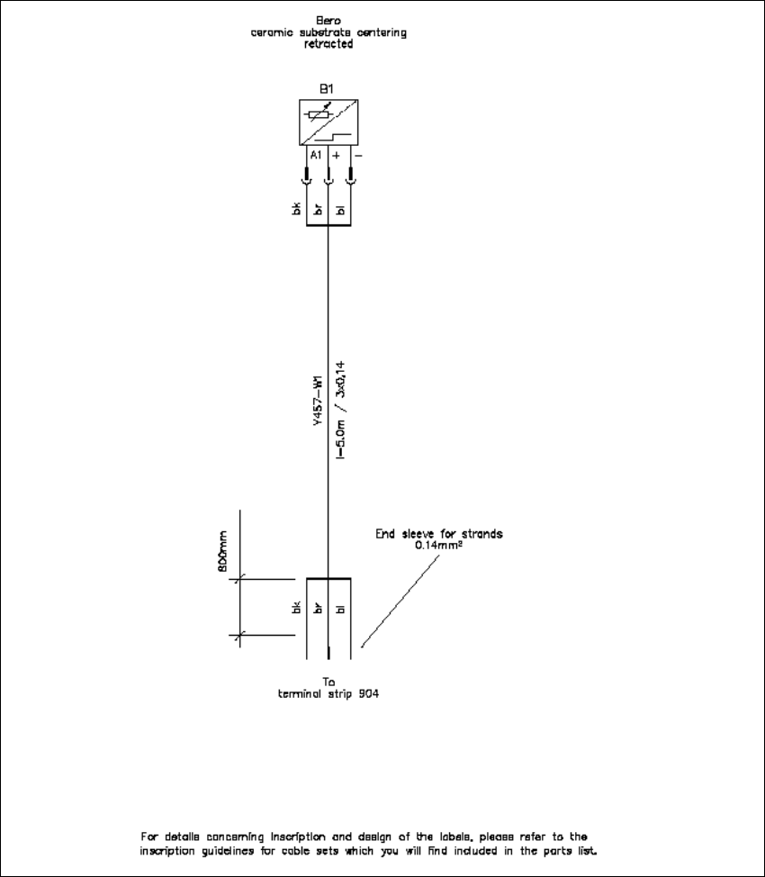
Fig. 2.6.2 Cable for Proximity Switch for SIPLACE 80 F4/F4-6/F5 and S20/S23HM
SIPLACE 80 S-20 / S-23HM/ F4 / F4-6 / F5 2 Retrofitting Instructions for Ceramic Substrate Centering Unit (Optional)
04/2000 Issue 2.6 Appendix: Cables and Circuit Drawings, Conversion PCB
67
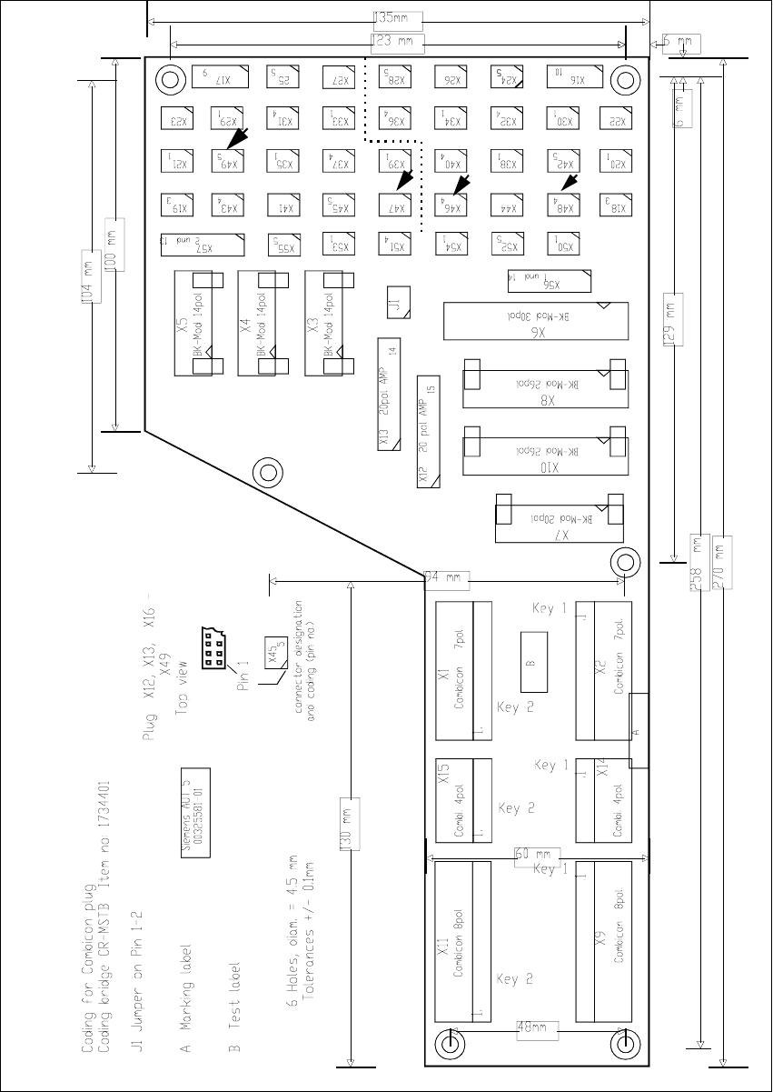
Fig. 2.6.3 Layout: Conversion PCB Conveyor Control (SIPLACE 80 S20/F4)