00194547-03.pdf - 第12页
Installation Manual Station Software Version 601.02 SP1 Edition 10/2005 12 of 82 3.2.2 Network configuration SIPLACE X series Station computer Machine controller 10Base-T 100Base-T Private network between station compute…
Installation Manual Station Software Version 601.02 SP1 Edition 10/2005
11 of 82
3.2 SIPLACE X series hardware components
3.2.1 Overview
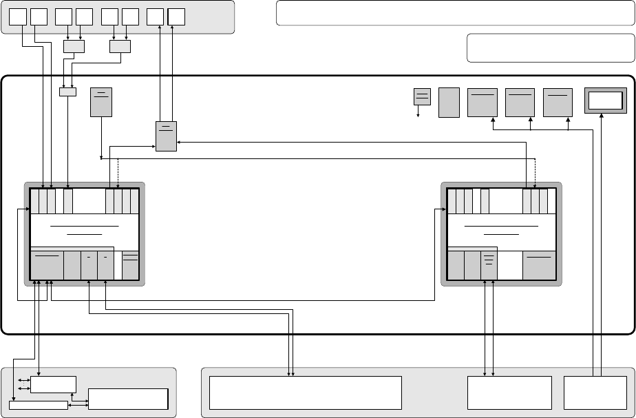
The following diagram show the hardware components of the computer system for the X-series
machine types:
Camera system for 2 processing areas with 2 - 4 placement heads
(C&P20/RV head and/or Twin Head) with component vision and PCB position
recognition and up to 2 x complanarity sensor option
(interfaces: sensor > RS485 > USB)
PS
Power supply
Computer unit
Fan unit
40 GB
HD
Manual MUX
switching only
used
(video data
(stationary
images) via hub)
CD ROM drive to
be connected
with the required
computer by
reconnecting the
USB cable
CPU07x-
ZUBLPT
Possibly VMP-HF version with only 1 x VGA
input and 2 x VGA outputs (connect 1 VGA
cable to one of the 2 computers)
PS DC-DC
+-12V / 6A
KSP SV501
PS DC-DC
+3.3V / 20A
KSP NTS50-3
PS DC-DC
+5.0V / 60A
KSP NTS50-5
+24 V
+52 V
Production line
LAN (hub)
Customer LAN
1 2
CAN bus
Decentralized controller
Machine
Y cable
Touch
screen 1
User
interface
Keyboard Y
adapter
Mouse Y
adapter
Video
Multi-
plexer
Touch
screen 2
Keyboard
1
Keyboard
2
Mouse
1
Mouse
2
Monitor
1
Monitor
2
Structure of the computer unit with its interfaces
SIPLACE Pro
programming system
Programming system
and external networks
LAN
Possibly switch
control elements
to USB port
P M 1.6 GHz, ASP 768 MB
Station computer
SMP16-CPU086
+3.6V
Buffer
battery
to
CPUs
Bay
R
E
S
E
R
V
E
SIPLACE X2/X3/X4
series / software: PF IIplus / 2-computer mode
C P C I B u s
LAN HUB .
1 2 1 2 3 4
KSP COM 294
Hot-
link
?
Hot-
link
?
R
E
S
E
R
V
E
CD
KSP
MEM365
L
A
N
C
O
M
A
C
O
M
B
V
G
A
U
S
B
1
U
S
B
2
K
E
Y
B
U
S
B
3
KSP
VMP-HF
40 GB
HD FD
CPCI-MEM371
C P C I B u s
Celeron 650 MHz, ASP 128 MB
Machine controller
SMP16-CPU076
CAN
1 2
CPCI-
COM
168
R
E
S
E
R
V
E
R
E
S
E
R
V
E
L
A
N
C
O
M
A
C
O
M
B
V
G
A
U
S
B
1
U
S
B
2
K
E
Y
B
Fig. 3-1: Hardware components of the computer system for the SIPLACE X series
Installation Manual Station Software Version 601.02 SP1 Edition 10/2005
12 of 82
3.2.2 Network configuration
SIPLACE X series
Station computer
Machine controller
10Base-T
100Base-T
Private network between
station computer and
machine controller
SIPLACE LAN
SIPLACE Pro
Twisted Pair TP
(100 MB)
Twisted Pair TP
(10 MB)
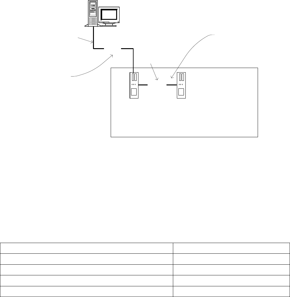
Fig. 3-2: Network connections between the machine and SIPLACE Pro using the example of the SIPLACE X series
A separate private network (100 Mbit) is set up between the station computer and the machine
controller via a subnet mask.
Fixed IP addresses for the station computer and the machine controller can thus be assigned for all
SIPLACE machines. These IP addresses are not known outside the private network, for instance in
the SIPLACE LAN.
These IP addresses need not be further configured by the operator while the station software is
being installed.
IP address, station computer 192.168.255.249
IP address, machine controller 192.168.255.250
Subnet mask, station computer/machine controller 255.255.255.248
IP address range, SIPLACE LAN 172.22.xxx.xxx
Subnet mask, SIPLACE LAN 255.255.0.0
Table 3-1: Network configuration

Installation Manual Station Software Version 601.02 SP1 Edition 10/2005
13 of 82
3.2.3 Station computer
Name SMP16-CPU086
CPU / clock frequency P M / 1.6 GHz
RAM 768 MB
Hard disk 40 GB
CD-ROM drive Yes
Serial interfaces 2
Network 1 x 10/100Base-T
2 x 10Base-T
6-port hub
Table 3-2: Station computer hardware
3.2.4 Machine controller
Name SMP16-CPU076
CPU / clock frequency Celeron / 650 MHz
RAM 128 MB
Hard disk 40 GB
Floppy drive 3.5", 1.44 MB
Network 1 x 10/100Base-T
Table 3-3: Machine controller hardware