00197975-06_UM_TX-Serie_EN.pdf - 第142页
3 Technical data and assemblie s User manual SIPLACE TX-Series 3.6 Gantry system From software version 713.0 Edition 01/2020 142 3.6.2 Position of gantries (1 gantry placement machine) 3 Fig. 3.6 - 2 Position of gantries…
User manual SIPLACE TX-Series 3 Technical data and assemblies
From software version 713.0 Edition 01/2020 3.6 Gantry system
141
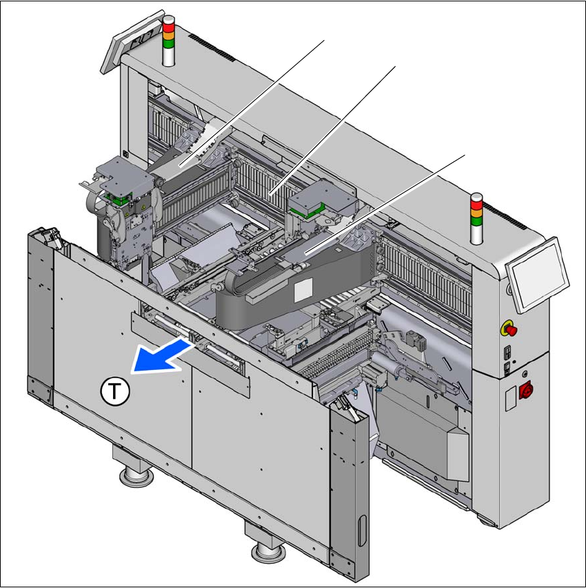
3.6 Gantry system
3.6.1 Position of gantries (2 gantry placement machine)
3
Fig. 3.6 - 1 Position of gantries - example of SIPLACE TX2 - location 2
(1) Gantry 1
(2) Y axis, gantry 1 and gantry 2
(3) Gantry 2
(T) Direction of PCB transport
(3)
(2)
(1)
3 Technical data and assemblies User manual SIPLACE TX-Series
3.6 Gantry system From software version 713.0 Edition 01/2020
142
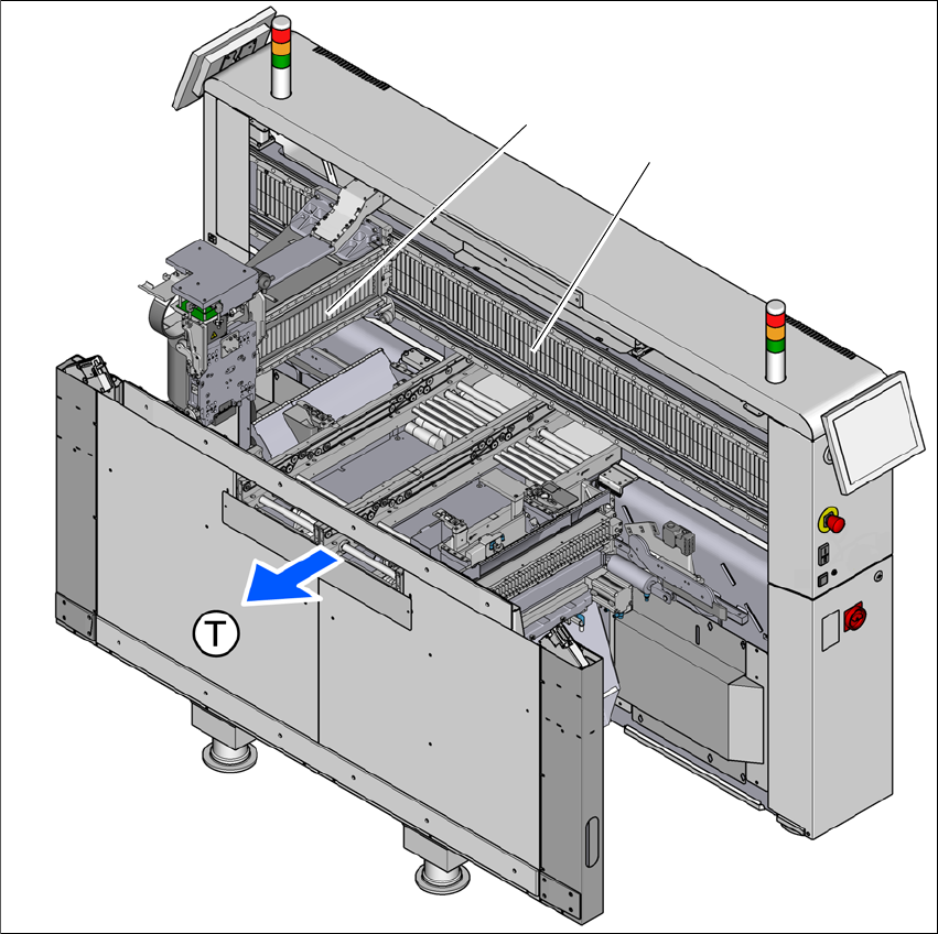
3.6.2 Position of gantries (1 gantry placement machine)
3
Fig. 3.6 - 2 Position of gantries in SIPLACE TX1 - location 2
(1) Gantry 1
(2) Y axis, gantry 1
(T) Direction of PCB transport
(1)
(2)
User manual SIPLACE TX-Series 3 Technical data and assemblies
From software version 713.0 Edition 01/2020 3.6 Gantry system
143
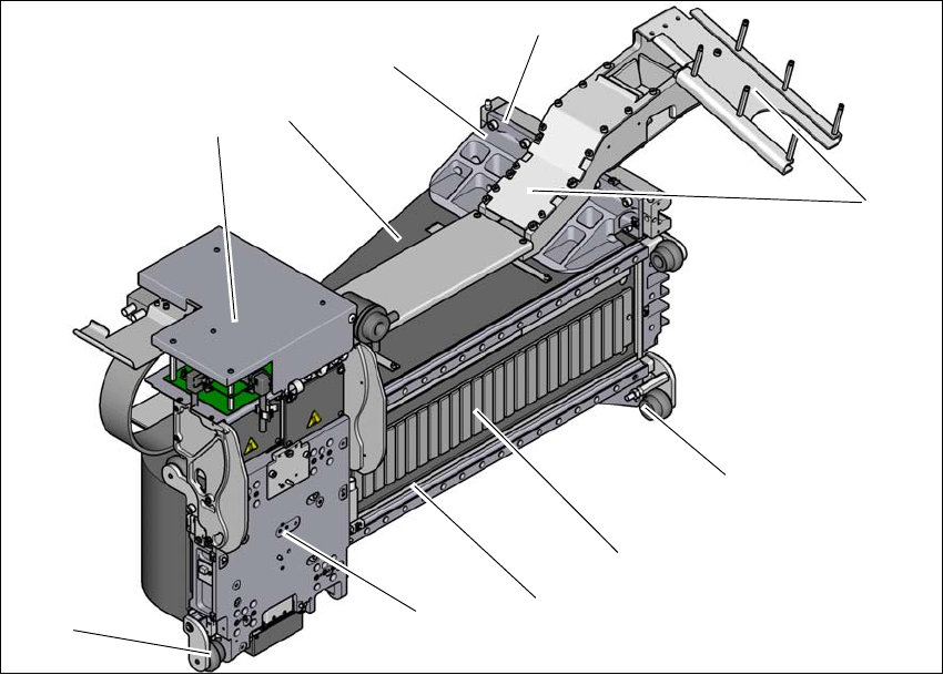
3.6.3 Gantry structure
3
Fig. 3.6 - 3 Gantry structure - view of head mount
(1) Head boards
(2) Gantry arm
(3) Y linear motor with fixed bearing (primary part)
(4) Mount for conversion board and trailing cable holder
(5) End position bumper (4x)
(6) Guidance system with permanent magnet (secondary part of the X linear motor)
(7) Length measurement system
(8) Head mount with X axis linear motor (primary part)
(9) Sensor module (for SIPLACE TX micron only)
(4)
(3)
(1)
(5)
(2)
(6)
(7)
(5)
(8)
(9)