00197975-06_UM_TX-Serie_EN.pdf - 第84页
2 Operational safety User manual SIPLACE TX-Series 2.5 Safety features From software version 713.0 Edition 01/2020 84 2.5.2.2 Position of the position switches on the pl acement machi ne 2 Fig. 2.5 - 4 Position of the po…
User manual SIPLACE TX-Series 2 Operational safety
From software version 713.0 Edition 01/2020 2.5 Safety features
83
2
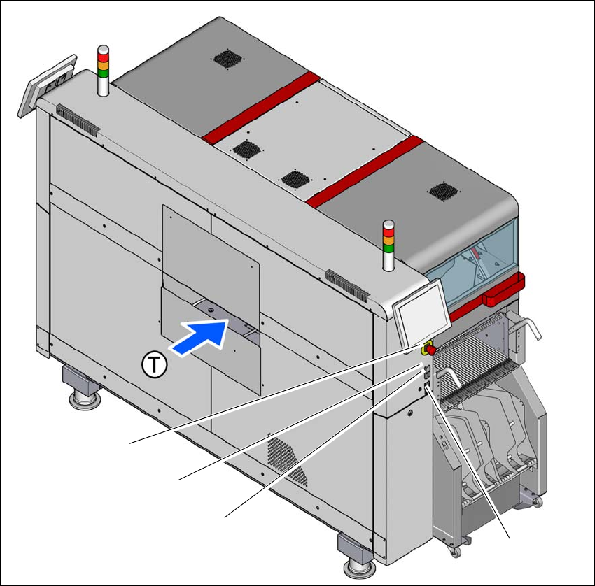
Fig. 2.5 - 3 Position of switches and buttons - PCB input end (location 1)
(1) EMERGENCY STOP button
(2) Start button (white)
(3) Stop button (black)
(4) Button for docking and undocking the component trolley at the respective location
(T) PCB transport direction
(3)
(1)
(4)
(2)
2 Operational safety User manual SIPLACE TX-Series
2.5 Safety features From software version 713.0 Edition 01/2020
84
2.5.2.2 Position of the position switches on the placement machine
2
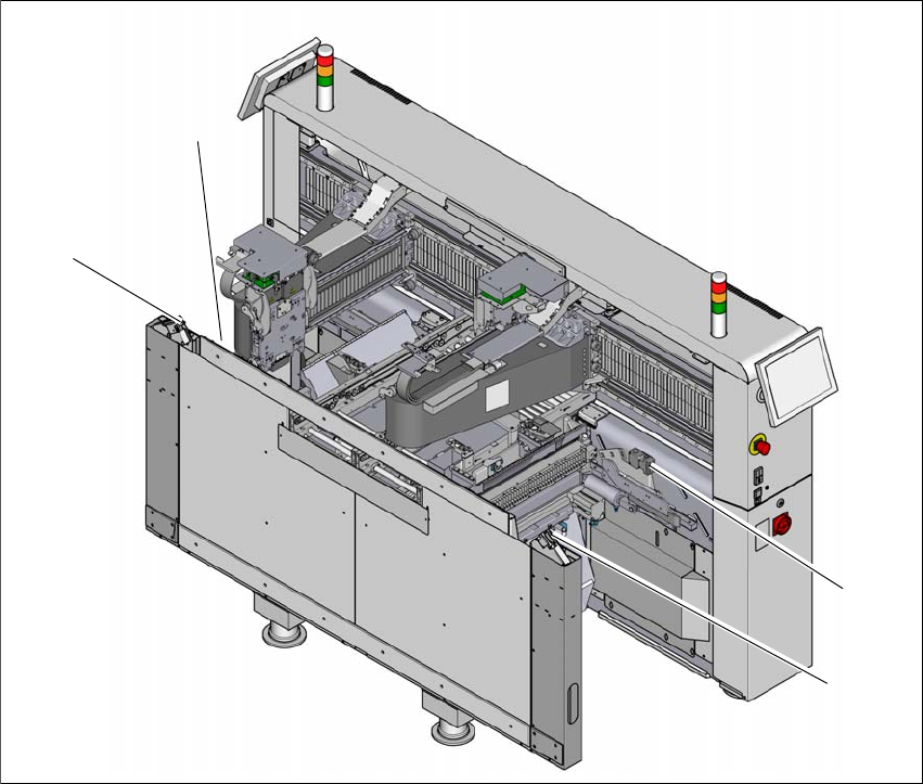
Fig. 2.5 - 4 Position of the position switches
(1) Position switches, location 1
(2) Protective switch for COT insert, location 1
(3) Protective switch for COT insert, location 2
(4) Position switches, location 2
The cover switches are mechanically locked during placement machine operation. The protective
covers can only be opened once the stop button has been pressed.
(4)
(1)
(3)
(2)

User manual SIPLACE TX-Series 2 Operational safety
From software version 713.0 Edition 01/2020 2.5 Safety features
85
2.5.2.3 Description of functions
Main switch in OFF position (see item 1 in fig.
2.5 - 2, page 82) 2
The main power switch disconnects the three phases L1, L2, and L3 from the power supply.
2
Main switch in ON position 2
When the main switch is switched to ON, the mains voltage is switched through to the power sup-
ply unit and all AC/DC converters are addressed.
The control computer will start and all supply voltages will be made available internally. The inter-
mediate circuit voltages for the gantry axes (300 V-) and star axes (160 V-) plus the supply voltage
for the conveyor drives are also connected via the start button for safety purposes.
DANGER
Incorrect handling of the placement machine can therefore result in death or severe injury
or considerable damage to equipment.
The following components still carry potentially lethal voltages even if the main power
switch is switched off:
– Cable connection terminals L1, L2, and L3 of the S1 main power switch
– Main input terminal X95
– Service socket X98 (if present)
– It can take up to 2 seconds until the residual voltage from the EMC filter has been
discharged at the power supply plug.
– Safety cutoff (CSB) still live for 5 minutes after switching off the main switch.
– The color of all individual wires, which are still live, even if the main switch is
switched off, is orange.
Always follow the applicable accident prevention and DIN regulations (particularly
EN 60204, part 1 or IEC 60204, part 1) and the applicable regulations in your own
country.
The safety door to the power supply must ONLY be opened by appropriately quali-
fied and trained personnel.