00198271-02_UM_ShuttleExtensionTX_EN.pdf - 第37页
Assembly and User Manual 3 Assembly Instruction Shuttle Extension Edition 06/2017 3.1 Scope of Delivery 35 3 Assembly Instruction 3.1 Scope of Delivery – Shuttle Extension: Item. No.: 588508 -xx – Transport rail position…
2 Operational safety Assembly and User Manual
2.4 ESD guidelines Shuttle Extension Edition 06/2017
34

Assembly and User Manual 3 Assembly Instruction
Shuttle Extension Edition 06/2017 3.1 Scope of Delivery
35
3 Assembly Instruction
3.1 Scope of Delivery
– Shuttle Extension: Item. No.: 588508-xx
– Transport rail position 281
– Mechanical Interface Kit: Item.No.:
– Shuttle Extension -Output bracket rear and front: Item. No.: 03148418-xx
– Shuttle Extension -Input bracket rear and front: Item. No.: 03148410-xx
– 2 x SMEMA Cable - for one Shuttle Extension: Item. No.: 03152800-xx
– One SMEMA cable for each lane.
– 1 x CAN Bus cable for one Shuttle Extension: Item. No.: 03133551-xx
– 1 x Power interface cable to SIPLACE TX: Item. No. 03123550-xx
3 Assembly Instruction Assembly and User Manual
3.1 Scope of Delivery Shuttle Extension Edition 06/2017
36
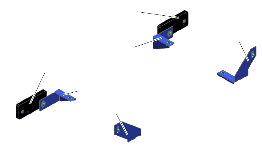
3.1.1 Mechanical Interface Kit
A mechanical interface kit will be used to fix Shuttle Extension into position. This mechanical in
-
terface kit consists of 2x Intermediate Ledges, 4x Interface brackets, 4x ISO4762 M8 and 8x
ISO7380-2 M8 screws. The Intermediate Ledge is mounted onto the SIPLACE TX feet, while the
Interface brackets are mounted on Shuttle Extension's body frame.
Fig. 3.1 - 1 Mechanical Interface Kit
(1) Intermediate ledge on SIPLACE TX output conveyor- right side
(2) Intermediate ledge on SIPLACE TX output conveyor- left side
(3) Interface bracket input Shuttle Extension- right side
(4) Interface bracket input Shuttle Extension - left side
(5) Interface bracket output Shuttle Extension - right side
(6) Interface bracket output Shuttle Extension - left side
(1)
(2)
(3)
(4)
(5)
(6)