00198271-02_UM_ShuttleExtensionTX_EN.pdf - 第50页
3 Assembly Instruct ion Assembly and User Manual 3.4 Electrical Connections Shuttle Extension Edition 06/2017 48 3.4.2.2 Connections The Shuttle Extension has two configurations, namely the upstre am and downstream, wiri…
Assembly and User Manual 3 Assembly Instruction
Shuttle Extension Edition 06/2017 3.4 Electrical Connections
47
3.4.2 SIPLACE TX Connection
3.4.2.1 Overview
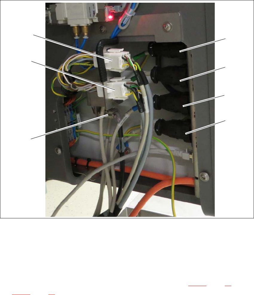
Fig. 3.4 - 2 SIPLACE TX Connection
(1) SMEMA connection T1 UPSTREAM
(2) SMEMA connection T1 DOWNSTREAM
(3) SMEMA connection T2 UPSTREAM
(4) SMEMA connection T2 DOWNSTREAM
(5) CAN-BUS Connection (for termination and connection see section 3.4.2.2
, page 48 and
3.4.2.3
, page 49)
(6) Power interface to the output Shuttle Extension
(7) Power interface to the input Shuttle Extension
(7)
(6)
(5)
(1)
(2)
(3)
(4)

3 Assembly Instruction Assembly and User Manual
3.4 Electrical Connections Shuttle Extension Edition 06/2017
48
3.4.2.2 Connections
The Shuttle Extension has two configurations, namely the upstream and downstream, wiring con
-
nections and jumpers setting are stated below.
3
For special configurations where two Shuttle Extensions are link to a single SIPLACE TX ma
-
chine, the CAN cable and TSP 420 jumper setting will be configure as per below.
3
Upstream configurations Downstream configurations
Power connection to TX -X15.S1 -X15.S2
CAN Bus connection to TX CAN3.EXT CAN3.EXT
Power connection to TX X50 X50
CAN Bus connection to Shuttle X52 X52
SMEMA connection to TX -XL1 and XL2 upstream -XL1 and XL2 downstream
SMEMA connection to Shuttle -XL1-DS and XL2-DS (Down
-
stream)
-XL1-US and XL2-US
(Upstream)
TSP 420 jumper setting JP1 pin 2 and 3 is shorted
JP2 pin 1 and 2 is shorted
JP1 pin 2 and 3 is shorted
JP2 pin 1 and 2 is shorted
CAN termination connector re
-
moved from CAN3.EXT
Plugged into -X1* (CAN ca
-
ble: upstream)
Plugged into -X1* (CAN ca
-
ble: downstream)
CAN cable IDC Connector Upstream configurations Downstream
configurations
-X1 -X1*(cable: downstream) CAN3.EXT (TX)
-X1* CAN termination connector
removed from CAN3.EXT
-X1 (cable: upstream)
-X52 -X52 (shuttle upstream) -X52 (shuttle downstream)
TSP 420 jumper setting
JP1 pin 2 and 3 is shorted
JP2 pin 1 and 2 is shorted
JP1 pin 2 and 3 is shorted
JP2 pin 1 and 2 is shorted
Assembly and User Manual 3 Assembly Instruction
Shuttle Extension Edition 06/2017 3.4 Electrical Connections
49
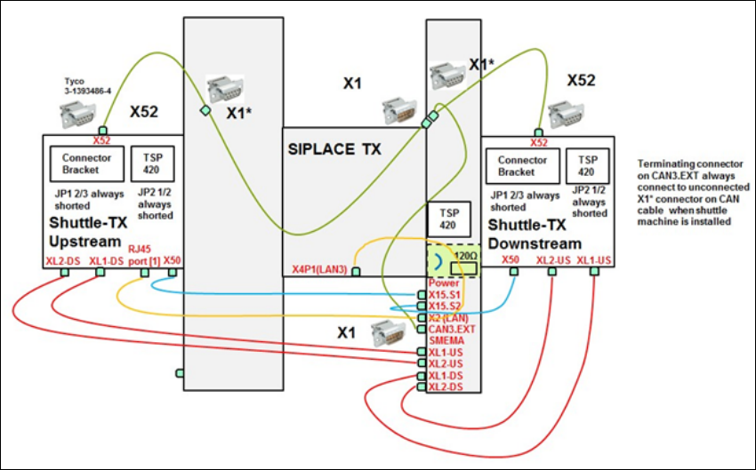
3.4.2.3 CAN cable connections for special configuration
Fig. 3.4 - 3 CAN cable connections for special configuration