00198271-02_UM_ShuttleExtensionTX_EN.pdf - 第40页
3 Assembly Instruct ion Assembly and User Manual 3.3 Installation Shuttle Extension Edition 06/2017 38 3.3 Installation 3.3.1 Overview Fig. 3.3 - 1 Mounting interfaces betw een SIPLACE TX & Shuttle Ex tension Fig. 3.…
Assembly and User Manual 3 Assembly Instruction
Shuttle Extension Edition 06/2017 3.2 Transporting the Shuttle Extension
37
3.2 Transporting the Shuttle Extension
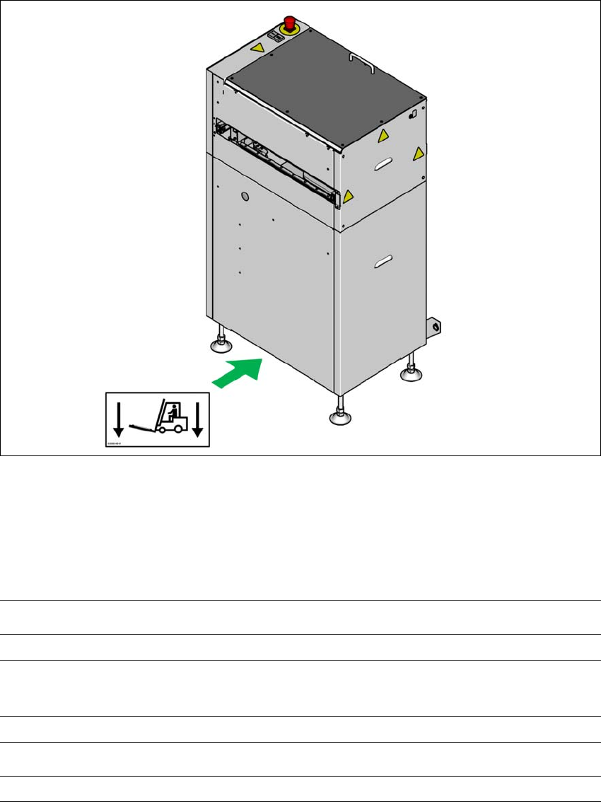
Fig. 3.2 - 1 Transporting the Shuttle Extension
The Shuttle Extension may ONLY be lifted with a pallet jack on the side (A).
3.2.1 Shipping packaging and Transportation Equipment
3
(A)
Shipping packaging dimensions (L x W x H)
Pallet 1105 mm x 905 mm x 1535 mm
Weight of the Shuttle Extension when ready for dispatch
With two Shuttle Extensions
170 kg
Transportation equipment
Pallet jack with fork length 700 mm
3 Assembly Instruction Assembly and User Manual
3.3 Installation Shuttle Extension Edition 06/2017
38
3.3 Installation
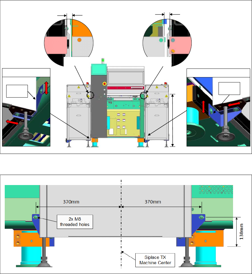
3.3.1 Overview
Fig. 3.3 - 1 Mounting interfaces between SIPLACE TX & Shuttle Extension
Fig. 3.3 - 2 Mounting holes position on SIPLACE TX machine frame (Input Side)
9
5
0
m
m
±
2
5
Siplace TX Input
Siplace TX Output
Interface
Bracket
Interface
Bracket
without sensor: 7.5mm – 10.5mm
with sensor: 10.5mm – 11mm
without sensor: 7.5mm – 10.5mm
with sensor: 10.5mm – 11mm
Assembly and User Manual 3 Assembly Instruction
Shuttle Extension Edition 06/2017 3.3 Installation
39
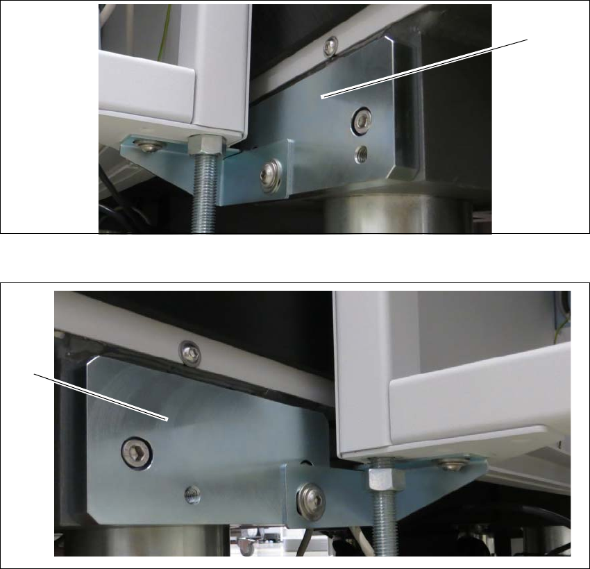
3.3.2 Mechanical Installation Procedure
Intermediate ledges on SIPLACE TX output conveyor side 3
Fit the two intermediate ledges to the machine feet of the SIPLACE TX output conveyor side.
Fig. 3.3 - 3 Intermediate ledge - right side
Fig. 3.3 - 4 Intermediate ledges -left side
(1) Intermediate ledge input conveyor - right side
(2) Intermediate ledge input conveyor - left side
(1)
(2)