00198271-02_UM_ShuttleExtensionTX_EN.pdf - 第46页
3 Assembly Instruct ion Assembly and User Manual 3.3 Installation Shuttle Extension Edition 06/2017 44 Interface brackets on output Shuttle Extension side 3 Fig. 3.3 - 11 Interface brackets on output conveyor - left side…
Assembly and User Manual 3 Assembly Instruction
Shuttle Extension Edition 06/2017 3.3 Installation
43
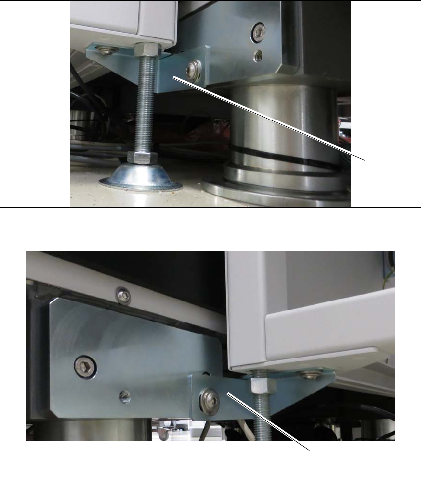
Interface brackets on input Shuttle Extension side 3
Fig. 3.3 - 9 Interface bracket on input conveyor - right side
Fig. 3.3 - 10 Interface bracket on input conveyor - left side
(1) Interface bracket input conveyor - right side
(2) Interface bracket input conveyor - left side
(1)
(2)
3 Assembly Instruction Assembly and User Manual
3.3 Installation Shuttle Extension Edition 06/2017
44
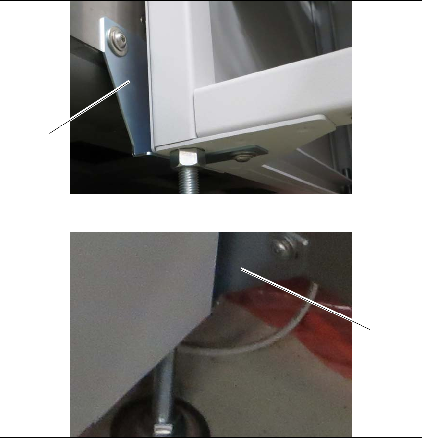
Interface brackets on output Shuttle Extension side 3
Fig. 3.3 - 11 Interface brackets on output conveyor - left side
Fig. 3.3 - 12 Interface brackets on output conveyor - right side
(1) Interface bracket output conveyor - left side
(2) Interface bracket output conveyor - right side
(1)
(2)

Assembly and User Manual 3 Assembly Instruction
Shuttle Extension Edition 06/2017 3.3 Installation
45
Finalize 3
Leave a gap of 2 mm to 8 mm between the frame of the SIPLACE TX and the frame of the
Shuttle Extension. See fig. 3.3 - 1
, page 38.
Check the transition between the Shuttle Extension and the SIPLACE TX again.
If necessary, correct the height at the feet or the fixture of the interface brackets.
Once the Shuttle Extension has been finally aligned, use the torque wrench to tighten top
screw nut (item 1 in see fig. 3.3 - 5
, page 40) to clamp all Shuttle Extension feet.