00198271-02_UM_ShuttleExtensionTX_EN.pdf - 第9页
Assembly and User Manual 1 Introduction Shuttle Extension Edition 06/2017 1.2 Overview 7 1.2 Overview 1.2.1 Shuttle Extension TX on SIPLACE TX Output Conveyor Side 1 Fig. 1.2 - 1 Shuttle Extension TX input side on SIPLAC…
1 Introduction Assembly and User Manual SIPLACE TX
1.1 Description Shuttle Extension Edition 06/2017
6
As an example, the following scenarios are possible:
– SIPLACE TX with dual conveyor (I-Placement) on a SIPLACE SX with dual conveyor (alter
-
nating mode).
– SIPLACE TX with dual conveyor on a printer or furnace.
The Shuttle Extension TX is always fitted to the SIPLACE TX. There is also a Shuttle Extension
TX available for the output end and a Shuttle Extension TX for the input end.
Assembly and User Manual 1 Introduction
Shuttle Extension Edition 06/2017 1.2 Overview
7
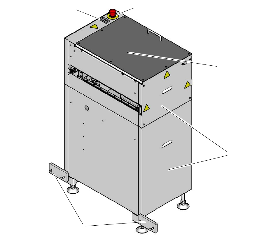
1.2 Overview
1.2.1 Shuttle Extension TX on SIPLACE TX Output Conveyor Side
1
Fig. 1.2 - 1 Shuttle Extension TX input side on SIPLACE TX output conveyor side
(T) Direction of travel from SIPLACE TX output conveyor
(1) Start- and Stop button
(2) EMERGENCY STOP button
(3) Top cover
(4) Side covers
(5) Interface brackets on SIPLACE TX output conveyor side
(1)
(5)
(2)
(3)
(4)
1 Introduction Assembly and User Manual SIPLACE TX
1.2 Overview Shuttle Extension Edition 06/2017
8
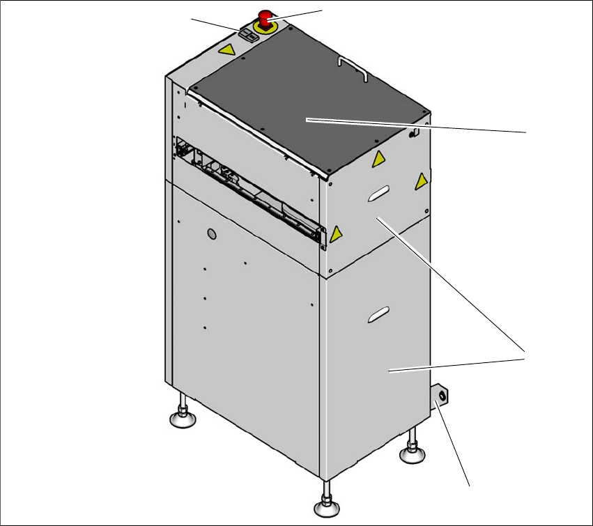
1.2.2 Shuttle Extension TX on SIPLACE TX Input Conveyor Side
1
Fig. 1.2 - 2 Shuttle Extension TX output side on SIPLACE TX input conveyor side
(T) Direction of travel to SIPLACE TX input conveyor
(1) Start- and Stop button
(2) EMERGENCY STOP button
(3) Top cover
(4) Side covers
(5) Interface brackets on SIPLACE TX input conveyor side
(1)
(5)
(2)
(3)
(4)