00198271-02_UM_ShuttleExtensionTX_EN.pdf - 第45页
Assembly and User Manual 3 Assembly Instruction Shuttle Extension Edition 06/2017 3.3 Installation 43 Interface brackets on input Shuttle Extension side 3 Fig. 3.3 - 9 Interface bracket o n input conveyor - right side Fi…
3 Assembly Instruction Assembly and User Manual
3.3 Installation Shuttle Extension Edition 06/2017
42
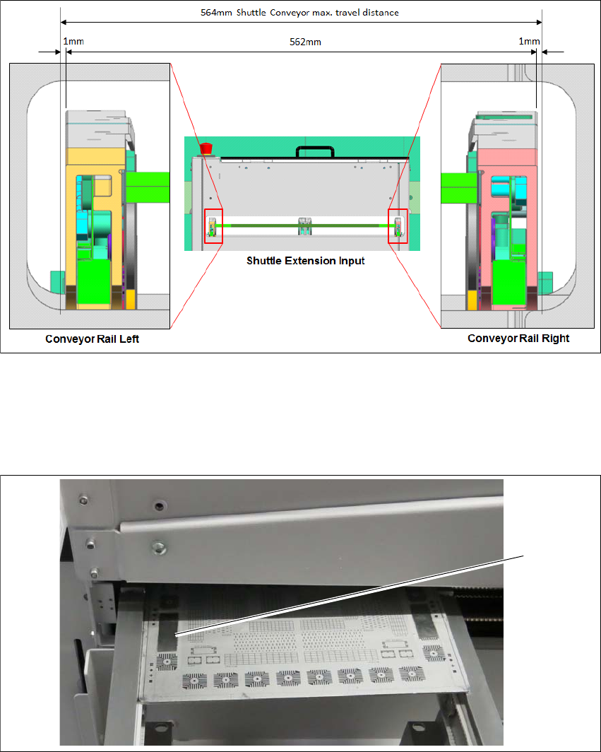
Shuttle Extension to SIPLACE TX Alignment 3
Fig. 3.3 - 7 Alignment position for Shuttle Extension
Shuttle conveyor rails to be positioned at 281 (1mm gap on each extreme end) and fixed with
motor brake.
Align one of the Shuttle conveyor rails (either left or right) to TX conveyor rail.
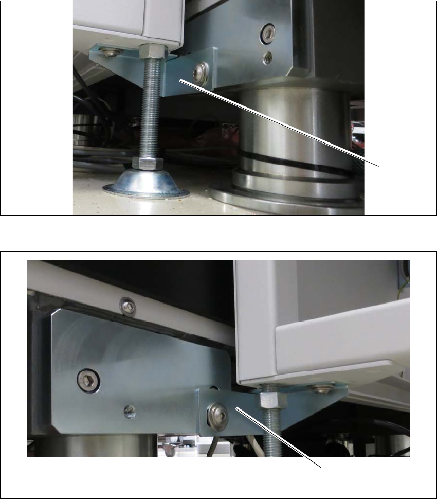
Fig. 3.3 - 8 Check PCB
Check rail position with the calibrated PCB.
Push a board through the PCB conveyor and check the transition point between the Shuttle
Extension and the SIPLACE TX.
It must be possible to push the board through easily and with no resistance.
Screw the Shuttle Extension onto TX machine via interface brackets to secure in place.
(1)
Assembly and User Manual 3 Assembly Instruction
Shuttle Extension Edition 06/2017 3.3 Installation
43
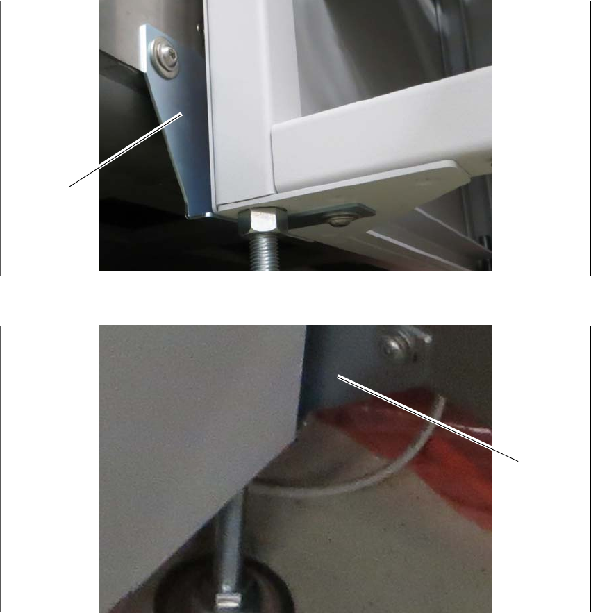
Interface brackets on input Shuttle Extension side 3
Fig. 3.3 - 9 Interface bracket on input conveyor - right side
Fig. 3.3 - 10 Interface bracket on input conveyor - left side
(1) Interface bracket input conveyor - right side
(2) Interface bracket input conveyor - left side
(1)
(2)
3 Assembly Instruction Assembly and User Manual
3.3 Installation Shuttle Extension Edition 06/2017
44
Interface brackets on output Shuttle Extension side 3
Fig. 3.3 - 11 Interface brackets on output conveyor - left side
Fig. 3.3 - 12 Interface brackets on output conveyor - right side
(1) Interface bracket output conveyor - left side
(2) Interface bracket output conveyor - right side
(1)
(2)