00198271-02_UM_ShuttleExtensionTX_EN.pdf - 第83页
Assembly and User Manual 6 Barcode Reader Extension Shuttle Extension Edition 06/2017 6.4 Assembly Instruction 81 6.4.15 Barcode R eaders - Wiring Connection 6 Fig. 6.4 - 15 Barcode Readers - Wiring Connection
6 Barcode Reader Extension Assembly and User Manual
6.4 Assembly Instruction Shuttle Extension Edition 06/2017
80
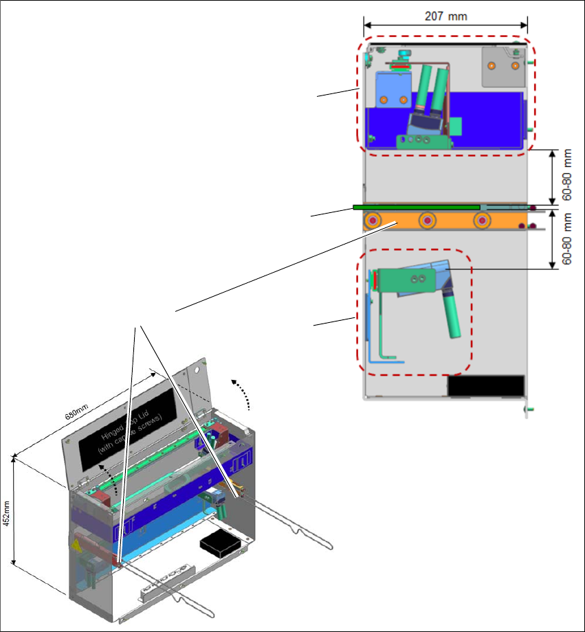
6.4.14 Barcode Readers - Overview
The default scanning distance for barcode reader is at 80 mm from the face of the PCB. Nonethe
-
less, both top and bottom barcode reader assembly can be adjusted to 60mm to allow reading
smaller code cells.
6
Fig. 6.4 - 14 Barcode Readers - Overview
Assembly kit PCB
Barcode Top
Assembly kit PCB
Barcode Bottom
PCB
Rail Extension +
Belt+ Pulleys
Assembly and User Manual 6 Barcode Reader Extension
Shuttle Extension Edition 06/2017 6.4 Assembly Instruction
81
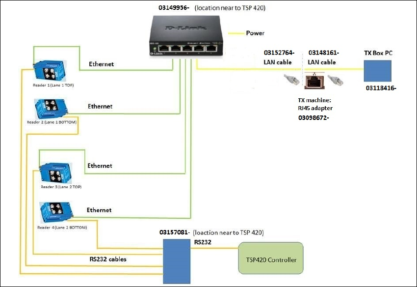
6.4.15 Barcode Readers - Wiring Connection
6
Fig. 6.4 - 15 Barcode Readers - Wiring Connection
6 Barcode Reader Extension Assembly and User Manual
6.5 Software Installation and Configuration Shuttle Extension Edition 06/2017
82
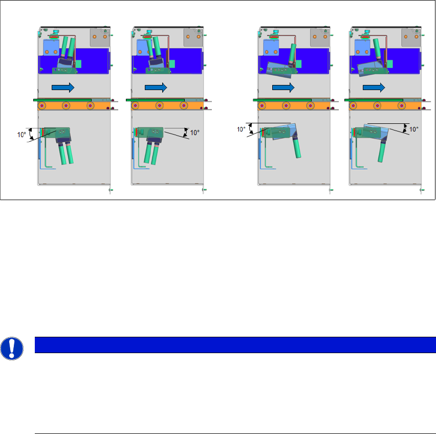
6.4.16 Barcode Reader Orientations and Tilted Angle
The barcode readers can be mounted in two orientations and be titled ±10° all round.
6
Fig. 6.4 - 16 Barcode Reader Orientations and Tilted Angle
6.5 Software Installation and Configuration
To install the SICK software "SOPAS" and to configure the 2D LECTOR 620 PCB barcode scan
-
ner, see the "Installation and Configuration Barcode Scanner SICK" manual [DE: 00198202 xx]
[EN: 00198203 xx].
6
Vertical Mount
Horizontal Mount
PCB
Direction
PCB
Direction
PLEASE NOTE
Further Information
For more information, please contact the SIPLACE service with reference to the following
numbers:.
– TI2016-05V03 / TI2016-05C03
– TI2015-12V06 / TI2015-12C06