00198761-01_SM_Head_Care_Station_II_EN.pdf - 第20页
3 Preparatory work... 3.3 Access to the spare parts of the HCS II Head Unit 20 Service Manual SIPLACE Head Care Station II 11/2019 3.3 Access to the spare parts of the HCS II Head Unit Fig.8: Remove covers ► Dismantle t…
3 Preparatory work...
3.1 Turn off and disconnect the HCS II
Service Manual SIPLACE Head Care Station II 11/2019 19
3 Preparatory work...
DANGER
Observe safety instructions!
► Please observe the safety instructions in this Service Manual and in the HCSII User
Manual for all work!
NOTICE
Observe the detailed circuit diagrams!
► For more detailed information refer to the circuit diagrams folder of the HCSII.
●
Detailed circuit diagrams folder for HCSII [DEEN:00198762‑xx]
3.1 Turn off and disconnect the HCS II
DANGER
Nonobservance may cause injury to personnel and damage to the HCS II!
► Before performing any service work on the HCS II, the following steps must be per-
form.
► End all verification operations at the HCS II.
► Close the SIPLACE Test Bench software.
► Shut down the Windows operating system correctly, otherwise problems may occur when
restarting or data may be lost.
► Switch off the HCS II at the main switch.
► Disconnect the HCS II from the main power supply.
► Disconnect the HCS II from the compressed air supply.
3.2 Equipment and tools
Equipment and tools needed to prepare the HCS II Head Unit for service work:
00353832‑xx Allen key set 2 mm, 2.5 mm
00376516-xx Socket wrench set 7 mm
00096290-xx Spanner wrench set 7 mm
00319064-xx Screwdriver Size 1
00318673-xx Side cutter electronic size 110
00096487-xx POINT PLIERS 140mm OVAL
00308458-xx Cable ties B=2.5mm, L=102mm Panduit
3 Preparatory work...
3.3 Access to the spare parts of the HCS II Head Unit
20 Service Manual SIPLACE Head Care Station II 11/2019
3.3 Access to the spare parts of the HCS II Head Unit
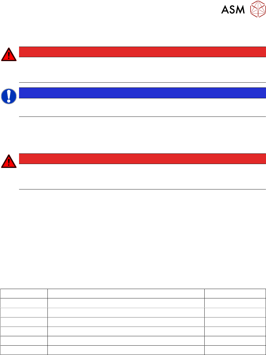
Fig.8: Remove covers
► Dismantle the placement head if avail-
able.
► Remove the cover(1).
► Disconnect the flat ribbon cables be-
hind the cover.
► Remove the five screws(2) fixing the
back cover(3) and put it down.
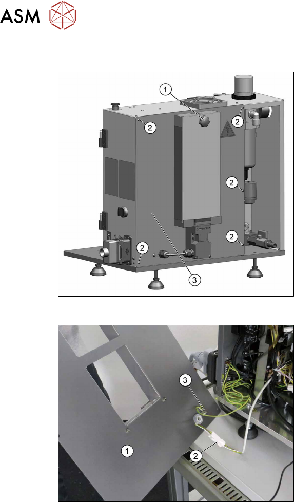
Fig.9: Remove covers
The back cover(1) is connected to the Head
Unit by a cable to the safety switch(2) and
an grounding cable(3).
► Unplug the cable to the safety
switch(2).
► You may want to remove the grounding
cable(3) for a better handling of the
Head Unit.
3 Preparatory work...
3.4 Access to the spare parts of the HCS II Control Box
Service Manual SIPLACE Head Care Station II 11/2019 21
3.4 Access to the spare parts of the HCS II Control Box
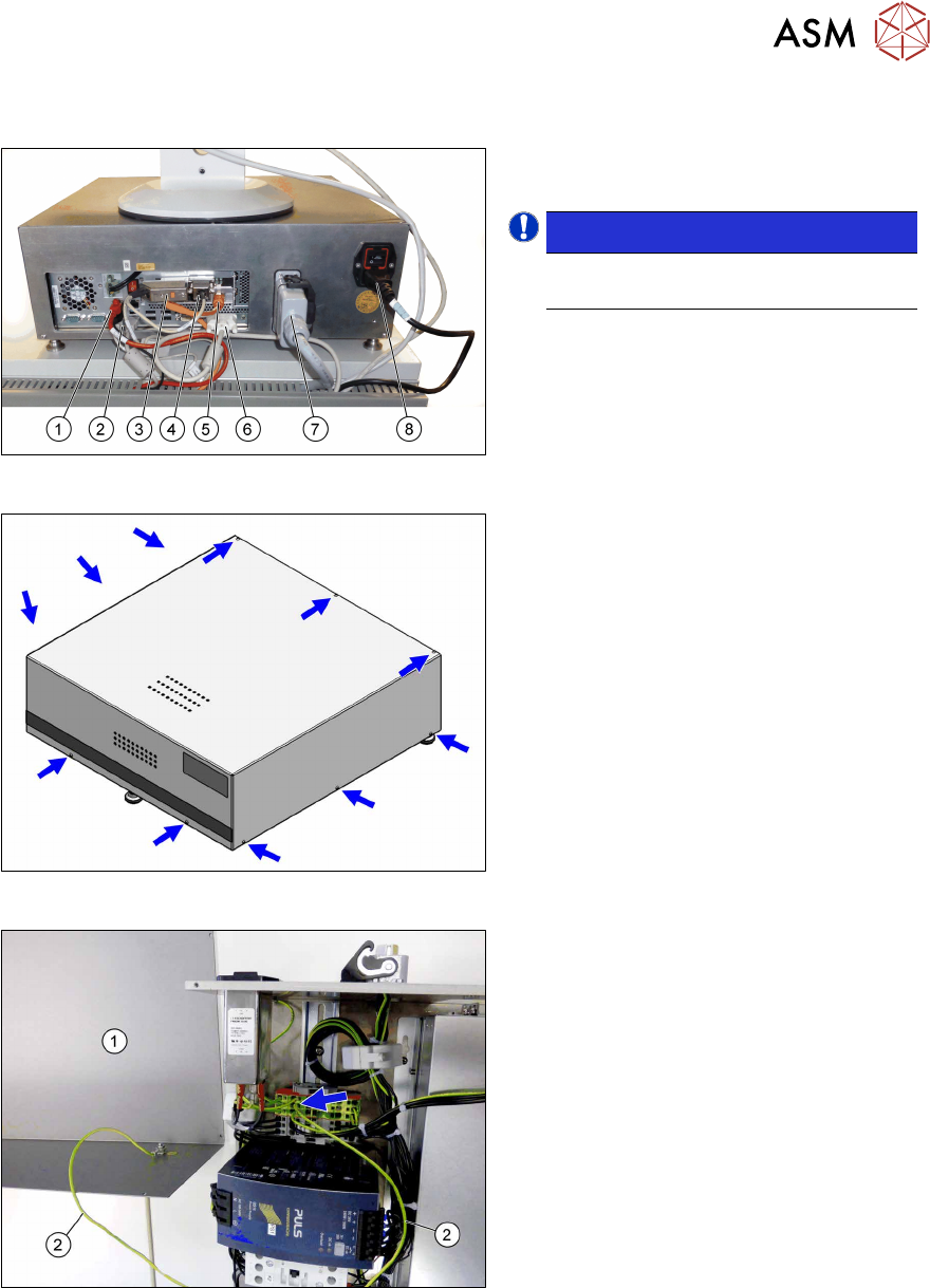
Fig.10: Disconnect cables
► Disconnect all cables(1) to(8) on the
back of the Control Box.
NOTICE!
Cables (3), (4) and (6) are fixed with
screws.
.
Fig.11: Remove screws
► Remove the eleven screws fastening
the cover.
Fig.12: Ground cable
The cover(1) is connected to the Control
Unit by a grounding cable(2).
► Carefully remove the cover.
► You may want to remove the grounding
cable for a better handling of the Con-
trol Box.