00198761-01_SM_Head_Care_Station_II_EN.pdf - 第47页
4 Service work – HCSII Head Unit 4.16 Replacing the Vision Hotlink Adapter Service Manual SIPLACE Head Care Station II 11/2019 47 Fig.66: Removal Cables ► Carefuly pull the Vision Hotlink Adapter VHA out of the frame. …
4 Service work – HCSII Head Unit
4.16 Replacing the Vision Hotlink Adapter
46 Service Manual SIPLACE Head Care Station II 11/2019
4.16 Replacing the Vision Hotlink Adapter
Parts
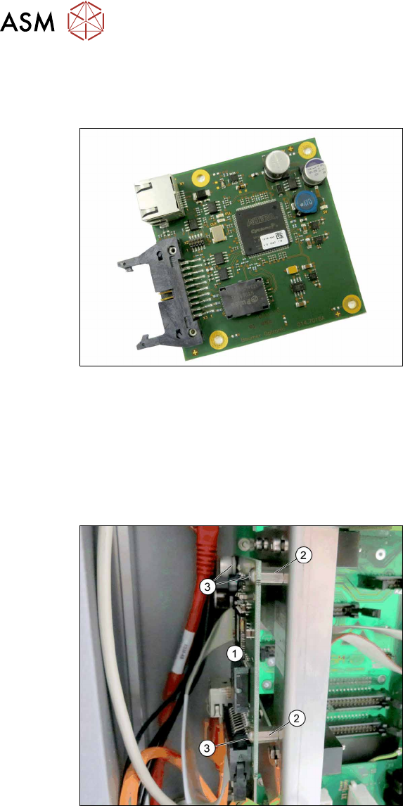
Fig.64: Vision Hotlink Adapter VHA
●
Vision Hotlink Adapter VHA
[03050555‑xx]
Preparatory work...
► Turn off and disconnect the HCS II. See 3.1 "Turn off and disconnect the HCS II" [}19].
► Perform the steps described in section 3.3 "Access to the spare parts of the HCS II Head
Unit" [}20].
Removal
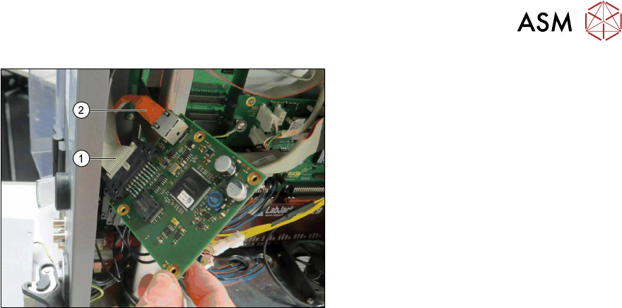
Fig.65: Removal PCB
► Open any cable ties where necessary.
► Remove the three screws(3) fastening
the Vision Hotlink Adapter VHA(1) on
the distance nuts(2). Make sure that
the screws are not lost.
.
4 Service work – HCSII Head Unit
4.16 Replacing the Vision Hotlink Adapter
Service Manual SIPLACE Head Care Station II 11/2019 47
Fig.66: Removal Cables
► Carefuly pull the Vision Hotlink Adapter
VHA out of the frame.
► You may want to mark the positions of
the relevant connections to make clear
assignment easier later on.
► Unplug the flat ribbon cable(1).
► Unplug the orange hot link cable(2).
► Carefully remove the Vision Hotlink
Adapter VHA.
Installation
► Follow the removal instructions in reverse order for installation.
► Replace any cable ties which you have removed.
4 Service work – HCSII Head Unit
4.17 Replacing the GigE Board
48 Service Manual SIPLACE Head Care Station II 11/2019
4.17 Replacing the GigE Board
Parts
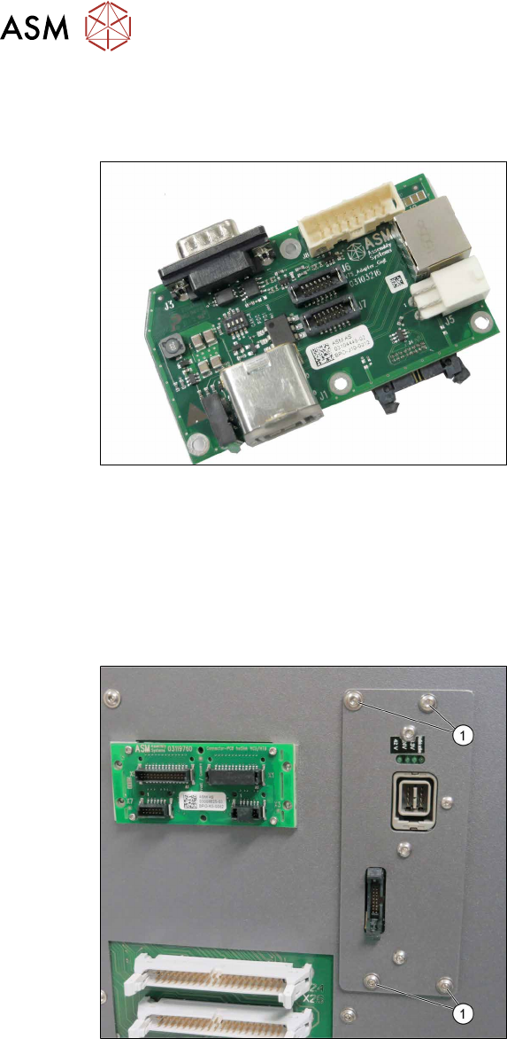
Fig.67: GigE Board
●
VTS board head camera GigE
[03104448‑xx]
Preparatory work...
► Turn off and disconnect the HCS II. See 3.1 "Turn off and disconnect the HCS II" [}19].
► Perform the steps described in section 3.3 "Access to the spare parts of the HCS II Head
Unit" [}20].
Removal
Fig.68: Removal 1
► Carefully remove the four screws(1)
fastening the GigE Board on the frame.
Hold the screw nuts from behind.
► Make sure that the screws are not lost.