00198761-01_SM_Head_Care_Station_II_EN.pdf - 第32页
4 Service work – HCSII Head Unit 4.6 Replacing the Base Adapter C&P / MHCU 32 Service Manual SIPLACE Head Care Station II 11/2019 Replacing/Converting the MHCUs ► Remove the screws (5) on the back of the board fast…
4 Service work – HCSII Head Unit
4.6 Replacing the Base Adapter C&P / MHCU
Service Manual SIPLACE Head Care Station II 11/2019 31
Fig.31: Removal 3
► Carefully move the Base Adapter C&P
a bit out (slight rotating movement).
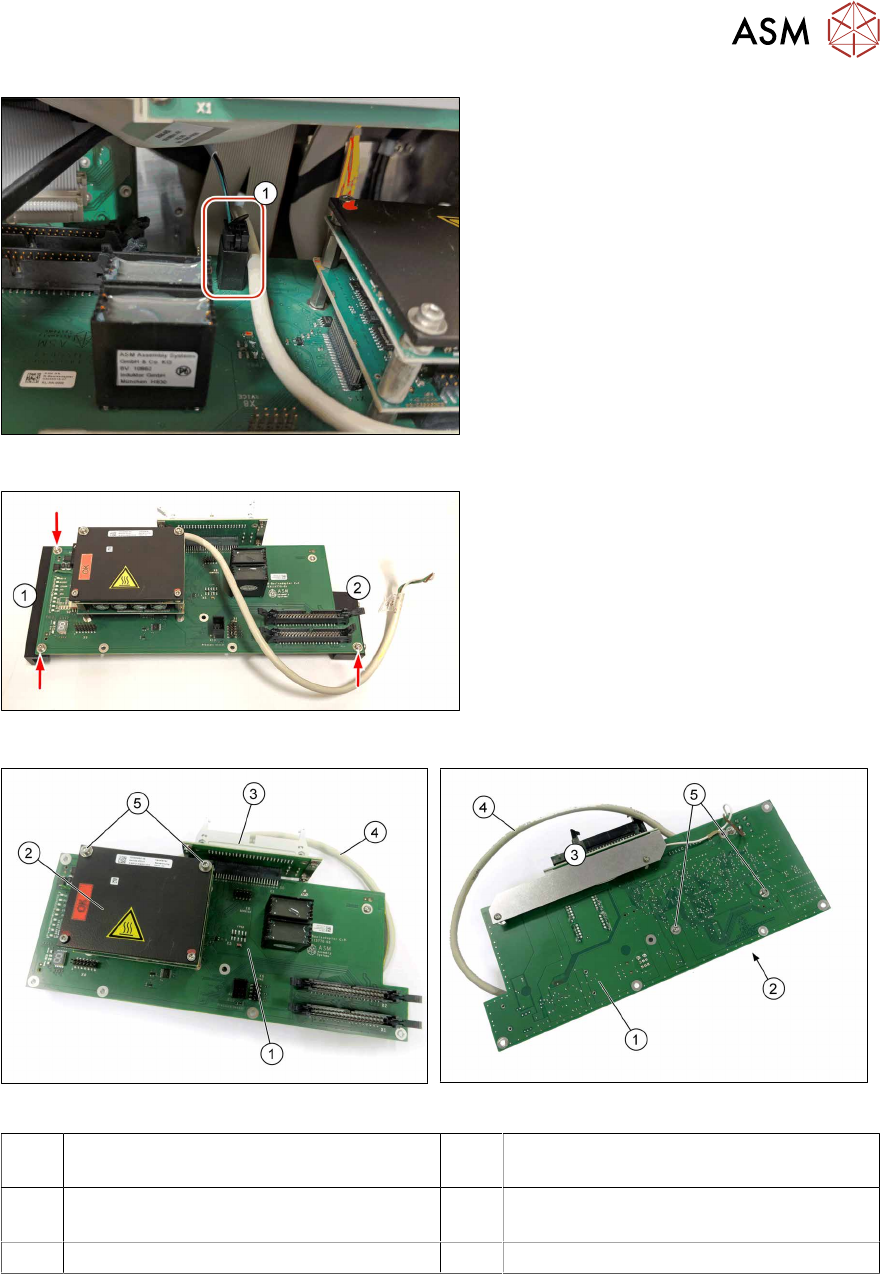
► Unplug the pressure sensor X10(1).
► Unthread the round cable X90 and
carefully remove the Base Adapter
C&P from the HCS.
Fig.32: Removal 4
► Remove the three screws fastening the
two assembly brackets(1) and(2).
Fig.33: Base Adapter C&P (upper side)
Fig.34: Base Adapter C&P (under side)
1 PCB Base Adapter C&P HCS2.3
[03158917‑xx]
2 MHCU complete compatible
[03090990‑xx]
3 Board Adapter-LP CPP/C&P20-HCSII
[03087843‑xx]
4 Round cable X90
5 Screws fastening the MHCU
► Remove the Board Adapter-LP CPP/C&P20-HCSII(3).
4.7 "Replacing the Board Adapter LP CPP/C&P20" [}33].
4 Service work – HCSII Head Unit
4.6 Replacing the Base Adapter C&P / MHCU
32 Service Manual SIPLACE Head Care Station II 11/2019
Replacing/Converting the MHCUs
► Remove the screws(5) on the back of the board fastening the MHCU(2) and carefully pull the
MHCU off the base adapter.
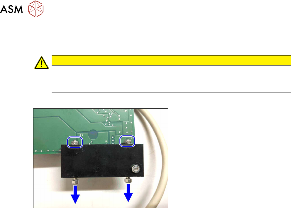
CAUTION
Washers/Pins
► Make sure not to loose the washers.
► Make sure not to damage the pins under the MHCU.
Installation
Fig.35: Installation
► Install the two assembly brackets on
the Base Adapter.
► Make sure that the assembly brackets
flush with the frame.
► To make installation easier, turn the
two screws at the smaller assembly
bracket out until they are barely visible
at the nuts.
► Install the Board Adapter-LP CPP/C&P20-HCSII.
4.7 "Replacing the Board Adapter LP CPP/C&P20" [}33].
► Insert the Base Adapter C&P into the HCS and thread in the round cable X90.
► Plug in the pressure sensor X10.
► Thread in the two screws on the left into the keyholes.
► Loosely insert the two screws on the right (the front one first).
► Push the Base Adapter C&P to the back and fasten the four screws.
► Plug in the two flat ribbon cables X1/X2 on the Base Adapter C&P.
(Make sure the plugs are locked on both sides.)
► Plug in the black cable X5 at the Modul Head Interface.
► Plug in the round cable X90 at the Board Adapter Head Interface (main PCB at the back side).
► Plug in the two flat ribbon cables at the Board adapter.
► Replace any cable ties which you have removed.
4 Service work – HCSII Head Unit
4.7 Replacing the Board Adapter LP CPP/C&P20
Service Manual SIPLACE Head Care Station II 11/2019 33
4.7 Replacing the Board Adapter LP CPP/C&P20
Parts
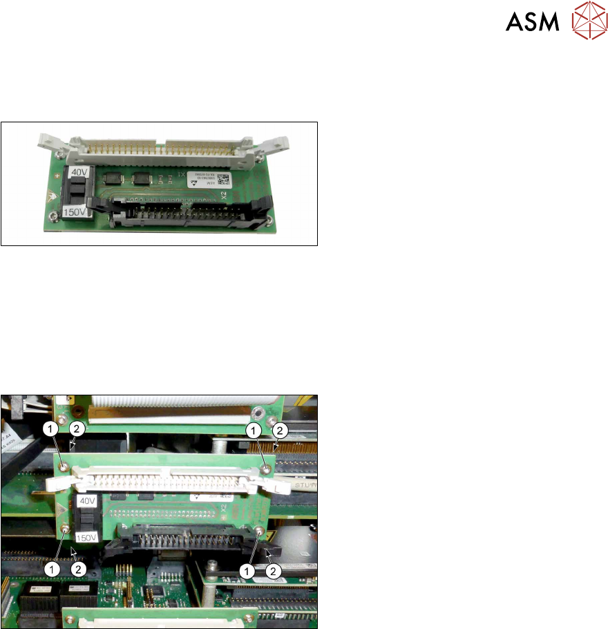
Fig.36: Board Adapter-LP CPP/C&P20 HCSII
●
Board Adapter-LP CPP/C&P20 HCSII
[03087843‑xx]
Preparatory work...
► Turn off and disconnect the HCS II. See 3.1 "Turn off and disconnect the HCS II" [}19].
► Perform the steps described in section 3.3 "Access to the spare parts of the HCS II Head
Unit" [}20].
Removal
Fig.37: Removal
► Unplug the flat ribbon cables
► Remove the four screws(1) fastening
the Board Adapter-LP CPP/C&P20 on
the Base Adapter C&P.
► Hold the screw nuts(2) from behind
(e.g.with tweezers).
► Make sure that the screws and screw
nuts are not lost.
Installation
► Follow the removal instructions in reverse order for installation.
► Replace any cable ties which you have removed.