00198761-01_SM_Head_Care_Station_II_EN.pdf - 第63页
5 Service work – HCSII Control Box 5.8 Replacing the Hotlink Interface Service Manual SIPLACE Head Care Station II 11/2019 63 5.8 Replacing the Hotlink Interface Parts Fig.93: Hotlink Interface PCI-A24-K01 ● Hotlink In…
5 Service work – HCSII Control Box
5.7 Replacing the CAN card
62 Service Manual SIPLACE Head Care Station II 11/2019
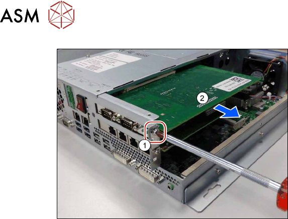
Fig.92: Removal 3
► Remove the screw(1).
► Carefully remove the CAN card(2).
Installation
► Follow the removal instructions in reverse order for installation.
► Replace any cable ties which you have removed.
5 Service work – HCSII Control Box
5.8 Replacing the Hotlink Interface
Service Manual SIPLACE Head Care Station II 11/2019 63
5.8 Replacing the Hotlink Interface
Parts
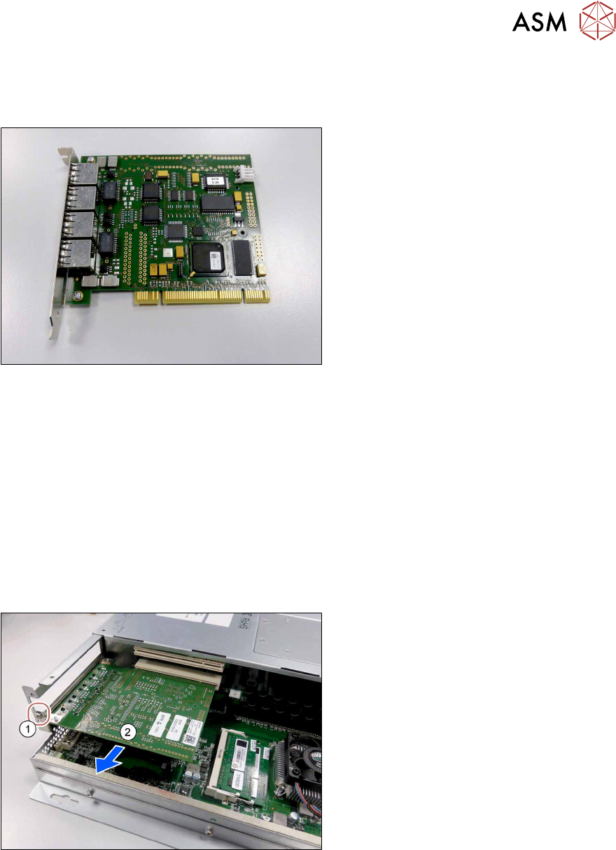
Fig.93: Hotlink Interface PCI-A24-K01
●
Hotlink Interface PCI-A24-K01
[03052135‑xx]
Preparatory work...
► Turn off and disconnect the HCS II. See 3.1 "Turn off and disconnect the HCS II" [}19].
► Perform the steps described in section 3.4 "Access to the spare parts of the HCS II Control
Box" [}21].
What to consider before the removal
To remove this assembly from the HCS II, remove the following assemblies, first. The fasteners
and connectors are accessible and you can remove this assembly.
► Remove the CAN card from the BoxPC. See 5.7 "Replacing the CAN card" [}61].
Removal
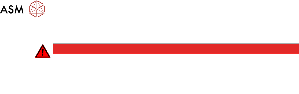
Fig.94: Removal 1
► Remove the screw(1).
► Carefully remove the Hotlink Inter-
face(2).
Installation
► Follow the removal instructions in reverse order for installation.
► Replace any cable ties which you have removed.
5 Service work – HCSII Control Box
5.9 Checking/Adjusting voltage
64 Service Manual SIPLACE Head Care Station II 11/2019
5.9 Checking/Adjusting voltage
DANGER
Hazardous voltage
Death, serious injury or considerable damage may result if the power supply is handled
incorrectly.
Only SIPLACE service technicians or adequately trained personnel, e.g. certified electrical
specialist, are allowed to perform this task on the power supply.