00198761-01_SM_Head_Care_Station_II_EN.pdf - 第51页
5 Service work – HCSII Control Box 5.1 Equipment and tools Service Manual SIPLACE Head Care Station II 11/2019 51 5 Service work – HCSII Control Box DANGER Observe safety instructions! ► Please observe the safety instr…
4 Service work – HCSII Head Unit
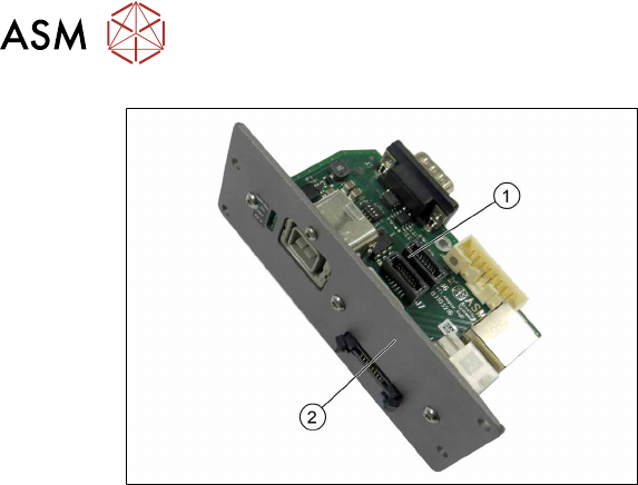
4.17 Replacing the GigE Board
50 Service Manual SIPLACE Head Care Station II 11/2019
Fig.71: Removal 4
► Remove the assembly frame(2) from
the GigE Board(1).
Installation
► Follow the removal instructions in reverse order for installation.
► Replace any cable ties which you have removed.
5 Service work – HCSII Control Box
5.1 Equipment and tools
Service Manual SIPLACE Head Care Station II 11/2019 51
5 Service work – HCSII Control Box
DANGER
Observe safety instructions!
► Please observe the safety instructions in this Service Manual and in the HCSII User
Manual for all work!
NOTICE
Observe the detailed circuit diagrams!
► For more detailed information refer to the circuit diagrams folder of the HCSII.
●
Detailed circuit diagrams folder for HCSII [DEEN:00198762‑xx]
5.1 Equipment and tools
Equipment and tools needed for service work on the HCSII Control Box:
00319064-xx Screwdriver philips Size 1
00353832‑xx Allen key set 2 mm, 2.5 mm, 3 mm
00096290-xx Spanner wrench set 5.5 mm, 10 mm
Slot screwdriver set Size 1, size 2
00096487-xx Angled tweezers 140mm oval
00318673-xx Side cutter electronic Size 110
00308458-xx Cable ties B=2.5mm, L=102mm Panduit
00198498‑xx Installation manual "WES7 and SW709.1 for
HCS"
5.2 Replacing the PCB Power Adjust HCSII compl. (PCB1/PCB2)
DANGER
Hazardous voltage
Death, serious injury or considerable damage may result if the power supply is handled
incorrectly.
Only SIPLACE service technicians or adequately trained personnel, e.g. certified electrical
specialist, are allowed to perform this task on the power supply.
Parts
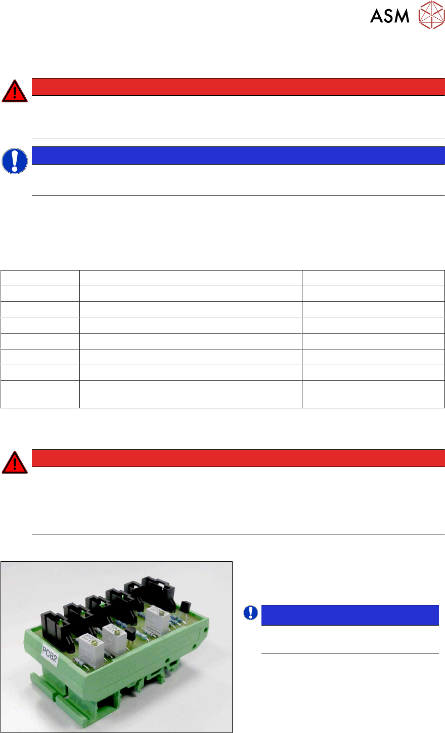
Fig.72: PCB Power Adjust HCSII compl.
●
PCB Power Adjust HCSII compl.
[03090149‑xx]
NOTICE!
PCB1 is connected to PS4.
PCB2 is connected to PS3.
.
5 Service work – HCSII Control Box
5.2 Replacing the PCB Power Adjust HCSII compl. (PCB1/PCB2)
52 Service Manual SIPLACE Head Care Station II 11/2019
Preparatory work...
► Turn off and disconnect the HCS II. See 3.1 "Turn off and disconnect the HCS II" [}19].
► Perform the steps described in section 3.4 "Access to the spare parts of the HCS II Control
Box" [}21].
What to consider before the removal
There are two PCB modules, PCB1 and PCB2. Installation and removal is described based on
PCB2. For PCB1 first remove PCB2 and then proceed in the same manner for PCB1.
Removal
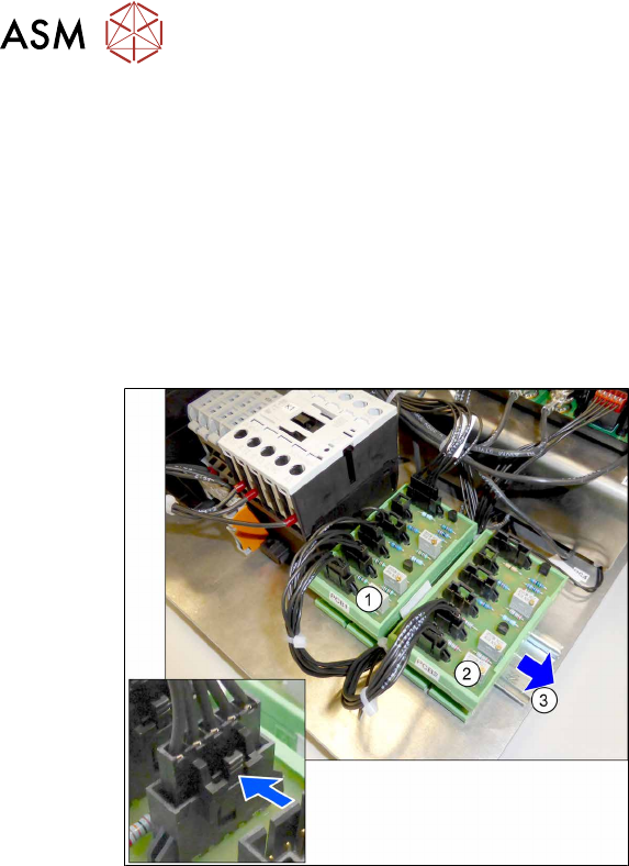
Fig.73: Removal
1. PCB1
2. PCB2
3. Rail
► Open any cable ties where necessary.
You may want to mark the positions of
the relevant connections to make clear
assignment easier later on.
► Unplug the cables from the PCB2(2).
► Pull the PCB2 to the side off the rail(3).
Installation
► Follow the removal instructions in reverse order for installation.
► Clip the new assembly on the rail from above.
► Label the new assembly with "PCB1" or "PCB2".
► Replace any cable ties which you have removed.
► Check/Adjust the voltage.
5.9 "Checking/Adjusting voltage" [}64]