00198761-01_SM_Head_Care_Station_II_EN.pdf - 第41页
4 Service work – HCSII Head Unit 4.13 Replacing the LabJack Service Manual SIPLACE Head Care Station II 11/2019 41 4.13 Replacing the LabJack Parts Fig.53: LabJack UE9 ● LabJack UE9 [03085251‑xx] Preparatory work... ► …
4 Service work – HCSII Head Unit
4.12 Replacing the Head Care Interface
40 Service Manual SIPLACE Head Care Station II 11/2019
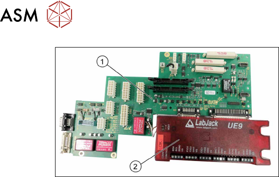
Fig.52: Head Care Interface with LabJack
1. Head Care Interface HCSII V2.3
[03149124‑xx]
2. LabJack UE9 [03085251‑xx]
► Remove the LabJack(2) from the Head
Care Interface(1). See 4.13 "Replacing
the LabJack" [}41].
Installation
Observe the sequence of the installation:
► Install the LabJack on the Head Care Interface. See 4.13 "Replacing the LabJack" [}41].
► Insert the Head Care Interface into the frame and connect the cables (X31, X19, X20, X19,
X6, grounding connection).
► Put the Head Care Interface in position and thighten the screws.
► Install the LabJack USB connection.
► Connect the cables X90, X102, X1, J1, J2, X15 to X18 (coded), X2, X107 (not used).
► Tighten the four distance nuts fastening the front connections on the outside of the casing.
► Install the fan (X26).
► Install the contactors K3 and K4. See 3.5 "Remove the contactors K3 and K4" [}22].
► Replace any cable ties which you have removed.
4 Service work – HCSII Head Unit
4.13 Replacing the LabJack
Service Manual SIPLACE Head Care Station II 11/2019 41
4.13 Replacing the LabJack
Parts
Fig.53: LabJack UE9
●
LabJack UE9 [03085251‑xx]
Preparatory work...
► Turn off and disconnect the HCS II. See 3.1 "Turn off and disconnect the HCS II" [}19].
► Perform the steps described in section 3.3 "Access to the spare parts of the HCS II Head Unit" [}20].
► Remove the contactors K3 and K4. See 3.5 "Remove the contactors K3 and K4" [}22].
► Remove the Head Care Interface with the LabJack. See 4.12 "Replacing the Head Care Inter-
face" [}38].
Removal
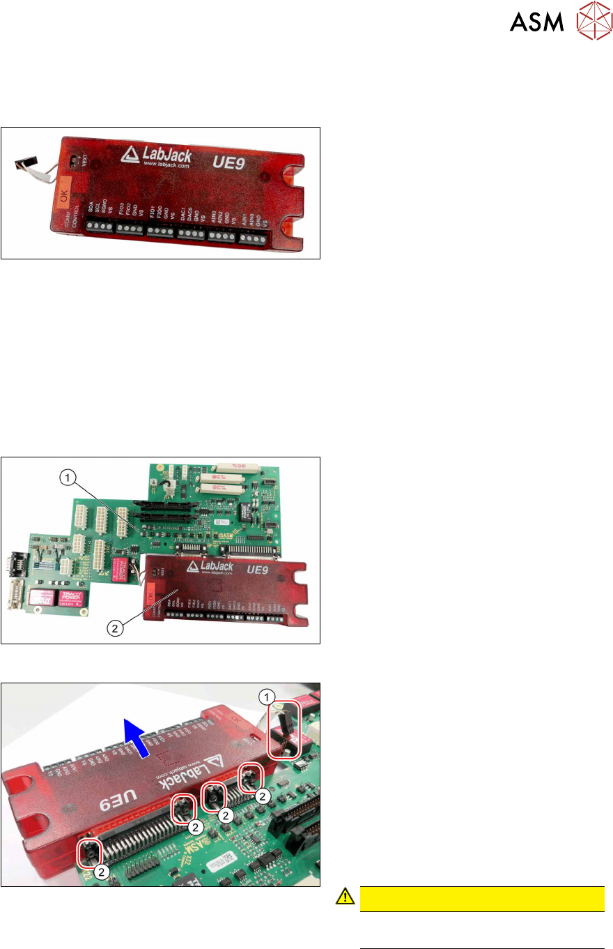
Fig.54: Head Care Interface with LabJack
1. Head Care Interface HCSII V2.3
[03149124‑xx]
2. LabJack UE9 [03085251‑xx]
Fig.55: Removal
► Open any cable ties where necessary.
You may want to mark the positions of
the relevant connections to make clear
assignment easier later on.
► Unplug the cable(1).
► Remove the four screws(2) fastening
the Head Care Interface(1) on the Lab-
Jack connectors. Make sure that the
screws are not lost.
► Remove the LabJack from the Head
Care Interface.
CAUTION!
Make sure that you do not damage
the pins.
.
Installation
► Follow the removal instructions in reverse order for installation.
► Replace any cable ties which you have removed.
4 Service work – HCSII Head Unit
4.14 Replacing the Board Adapter Head Interface C700B
42 Service Manual SIPLACE Head Care Station II 11/2019
4.14 Replacing the Board Adapter Head Interface C700B
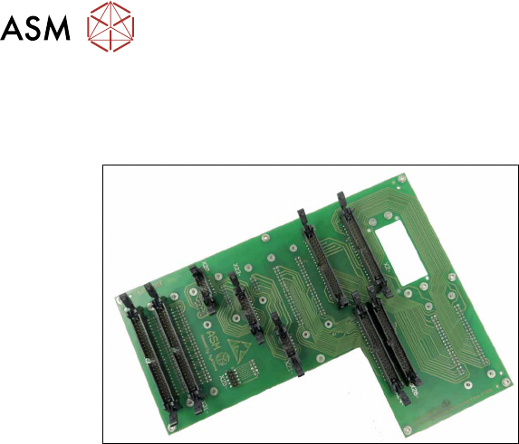
Parts
Fig.56: Board Adapter Head Interface
●
Board Adapter Head Interface
[03085198‑xx]
Preparatory work...
► Turn off and disconnect the HCS II. See 3.1 "Turn off and disconnect the HCS II" [}19].
► Perform the steps described in section 3.3 "Access to the spare parts of the HCS II Head
Unit" [}20].
► Remove the contactors K3 and K4. See 3.5 "Remove the contactors K3 and K4" [}22].
► Remove the compressed air filter. See 4.2 "Replacing the compressed air filter" [}24].
► Remove the PCB Base Adapter Twin. See 4.4 "Replacing the Base Adapter Twin /
MHCU" [}26].
► Remove the PCB Base Adapter C&P. See 4.6 "Replacing the Base Adapter C&P /
MHCU" [}29].
► Remove the Modul Head Interface-C700B. See 4.8 "Replacing the Head Interface-
C700B" [}34].
► Remove the Head Care Interface with the LabJack. See 4.12 "Replacing the Head Care Inter-
face" [}38].