00198761-01_SM_Head_Care_Station_II_EN.pdf - 第21页
3 Preparatory work... 3.4 Access to the spare parts of the HCS II Control Box Service Manual SIPLACE Head Care Station II 11/2019 21 3.4 Access to the spare parts of the HCS II Control Box Fig.10: Disconnect cables ► Di…
3 Preparatory work...
3.3 Access to the spare parts of the HCS II Head Unit
20 Service Manual SIPLACE Head Care Station II 11/2019
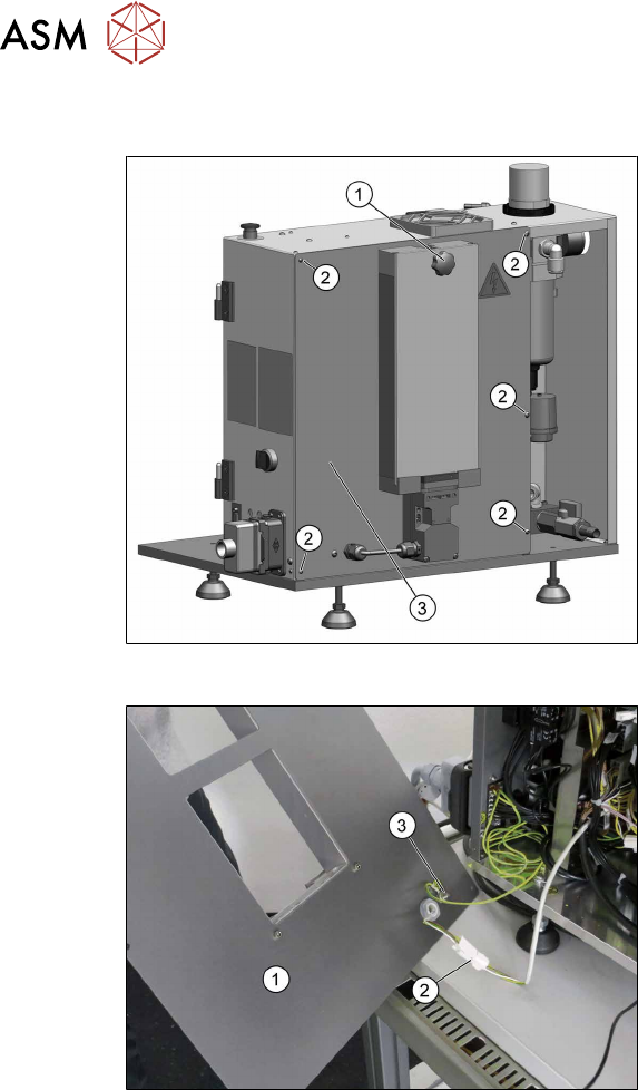
3.3 Access to the spare parts of the HCS II Head Unit
Fig.8: Remove covers
► Dismantle the placement head if avail-
able.
► Remove the cover(1).
► Disconnect the flat ribbon cables be-
hind the cover.
► Remove the five screws(2) fixing the
back cover(3) and put it down.
Fig.9: Remove covers
The back cover(1) is connected to the Head
Unit by a cable to the safety switch(2) and
an grounding cable(3).
► Unplug the cable to the safety
switch(2).
► You may want to remove the grounding
cable(3) for a better handling of the
Head Unit.
3 Preparatory work...
3.4 Access to the spare parts of the HCS II Control Box
Service Manual SIPLACE Head Care Station II 11/2019 21
3.4 Access to the spare parts of the HCS II Control Box
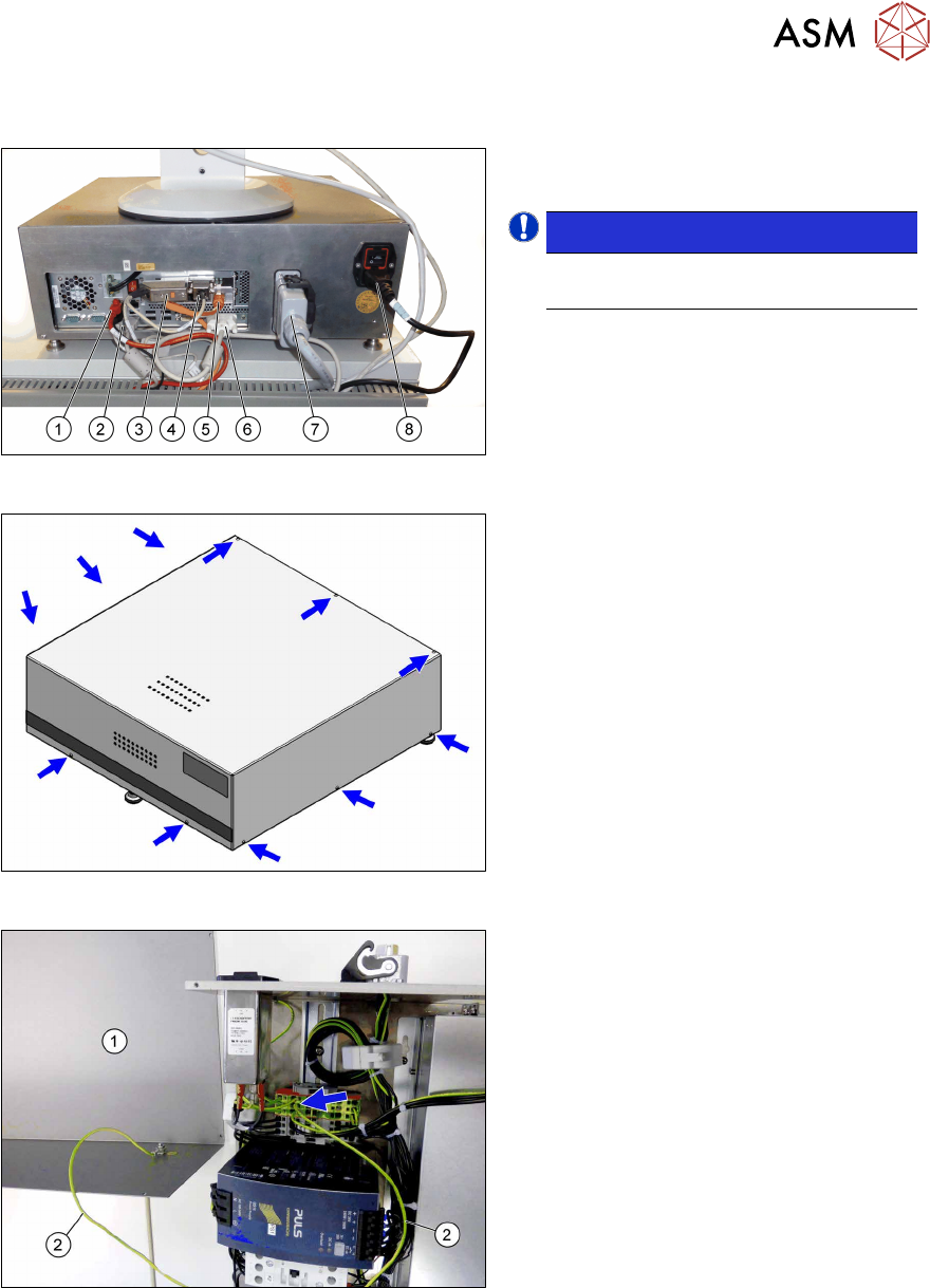
Fig.10: Disconnect cables
► Disconnect all cables(1) to(8) on the
back of the Control Box.
NOTICE!
Cables (3), (4) and (6) are fixed with
screws.
.
Fig.11: Remove screws
► Remove the eleven screws fastening
the cover.
Fig.12: Ground cable
The cover(1) is connected to the Control
Unit by a grounding cable(2).
► Carefully remove the cover.
► You may want to remove the grounding
cable for a better handling of the Con-
trol Box.
3 Preparatory work...
3.5 Remove the contactors K3 and K4
22 Service Manual SIPLACE Head Care Station II 11/2019
3.5 Remove the contactors K3 and K4
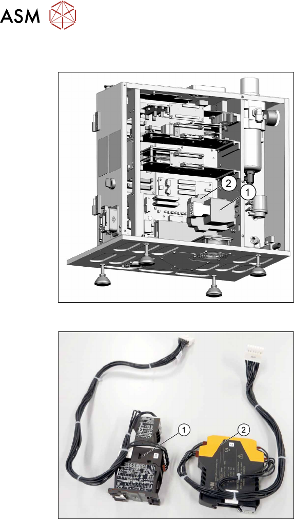
Fig.13: Remove contactors K3 and K4
1. K3 to X101
2. K4 to X100
► Remove the contactors K3(1) and
K4(2) for better access to all parts.
► Unplug the electrical connections. You
might like to mark their positions to
make clear assignment easier later on.
Fig.14: Contactors K3 and K4
Contactors removed
1. K3
2. K4