JO-116-001_w.pdf - 第112页
4-27 JO-1 16 1 105-001 2.1 Operation Procedure for [Measurement T ype 4] (6) When the conrmation guide message for the sprocket reference positioning operation start, is displayed, click [OK]. Click [OK]. Fig. D32 After…
4-26
JO-116
1105-001
2.1 Operation Procedure for [Measurement Type 4]
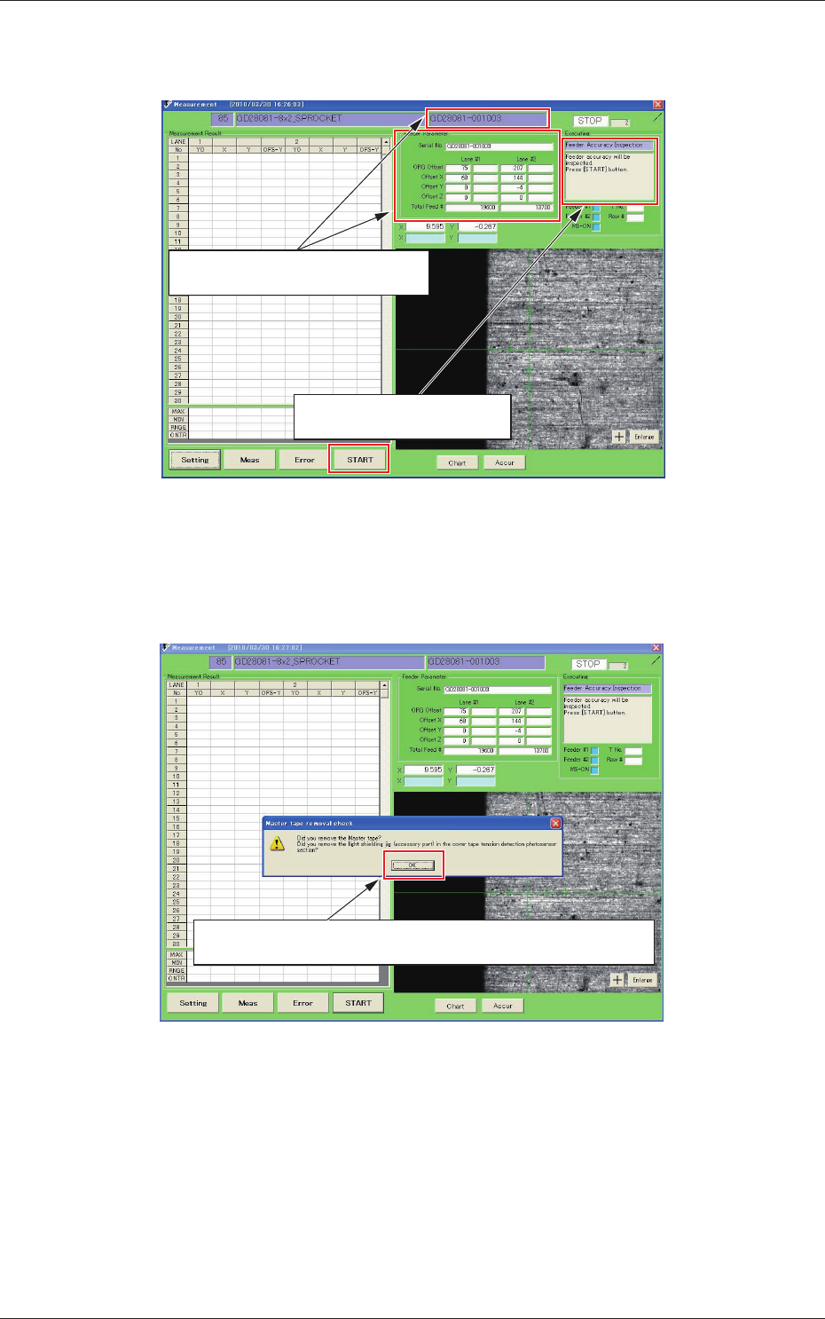
(4) When the feeder is connected to the jig, the feeder communication
is started and the parameters are read in.
When this message is displayed,
press the [START] button.
The feeder parameters are read and
displayed.
Fig. D30
(5) When the [START] button is pressed, the following conrmation
guide message is displayed.
When it is confirmed that the master tape and the light shading jig are
not set onto the feeder, click [OK].
Fig. D31
4-27
JO-116
1105-001
2.1 Operation Procedure for [Measurement Type 4]
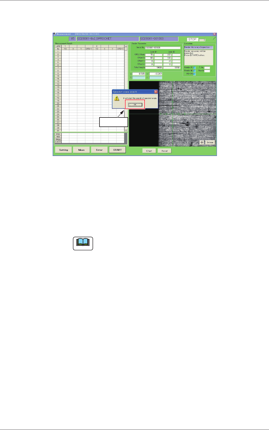
(6) When the conrmation guide message for the sprocket reference
positioning operation start, is displayed, click [OK].
Click [OK].
Fig. D32
After the communication with the feeder is started and the
parameter reading is performed, the feeder sprocket turns round
and the reference positioning operation is started up.
This operation is performed in the Lane 1 and Lane 2 in this
order.
Note
With the above procedure, the jig origin adjustment is ready.
4-28
JO-116
1105-001
2.1 Operation Procedure for [Measurement Type 4]
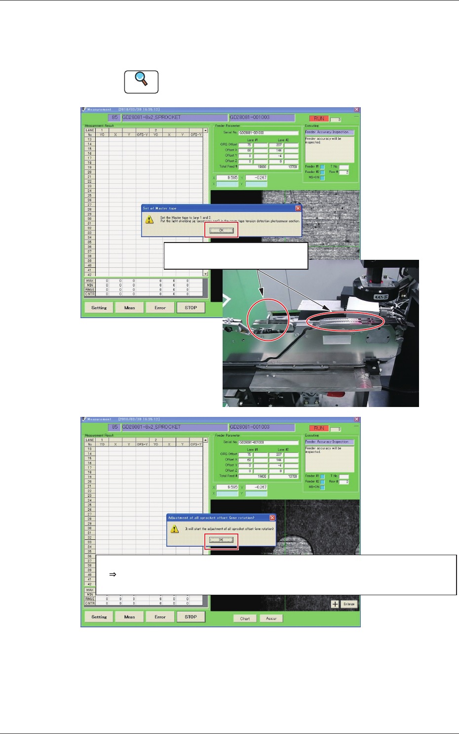
(7) When the sprocket reference positioning operation is completed,
the following operation guide message is displayed.
Then, attach the master tape and light shading jig correctly.
Reference
Refer to "2.3 Attachment and Detachment of Master Tapes" in
Section 4, for the attachment of the master tape.
Set the master tape and light shading
jig and click the [OK] button.
When the attachment is completed, click the [OK] button.
After that, the same adjustment operation procedure as for [Measurement Type 3] is performed.
Recognition mark position teaching, L1, L2 pick-up holes (every 45 perforations) teaching
Fig. D33