JO-116-001_w.pdf - 第128页
4-43 JO-1 16 1 105-001 3.2 Measuring Method (2) Raise the suppressor and perform the measurement as shown below . Measurement with GT -08080 (Example) Push down the feeder with your hand. Fig. D56 (3) See the gures belo…
4-42
JO-116
1105-001
3. Measurement of Jig Origin Height
3. Measurement of Jig Origin Height
3.1 Required Measuring Apparatuses
•
Block Gauge 104.00 mm
Ref.
: Several block gauges can be piled up to be 104.00 mm.
•
Pry-Type Dial Gauge 0.01 mm
•
Stand (used for the pry-type dial gauge)
•
Surface Plate Size: 300 mm × 300 mm or more
3.2 Measuring Method
Note
Perform the measurement on the surface plate.
Procedure
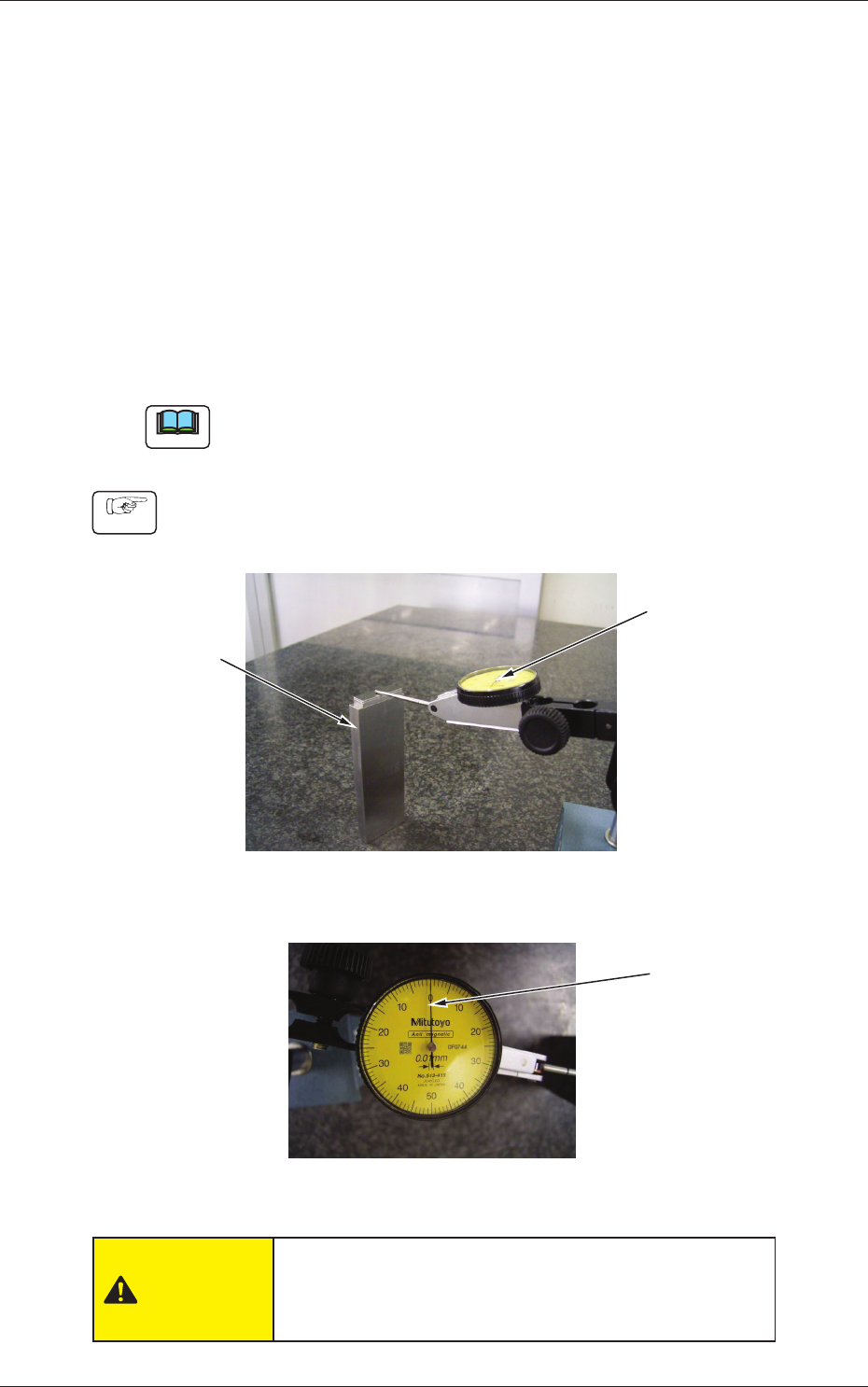
(1) Adjust the pointer of the pry-type dial gauge to "0" (zero), using
the block gauge (104.00).
Block Gauge
104.0 mm
Adjust the pointer
to "0" (zero).
Pry-Type Dial Gauge
Measurement on the surface plate
Fig. D55
CAUTION
Carefully handle the dial gauge because the tip of
the probe is very sharp. Your hand will get injured if
the tip is inserted.
4-43
JO-116
1105-001
3.2 Measuring Method
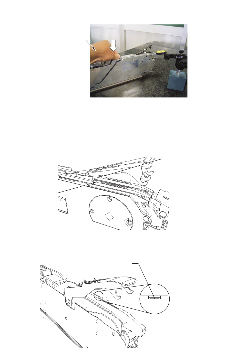
(2) Raise the suppressor and perform the measurement as shown
below.
Measurement with GT-08080 (Example)
Push down the feeder
with your hand.
Fig. D56
(3) See the gures below for the spots to be measured.
•
Measuring Position for G*-0808*
Measuring Position on
Lane #2 Side
Measuring Position on
Lane #1 Side
Fig. D57
•
G*-12160 or more
Measure the area beside
the fiducial mark.
Magnified View
Fig. D58
4-44
JO-116
1105-001
3.2 Measuring Method
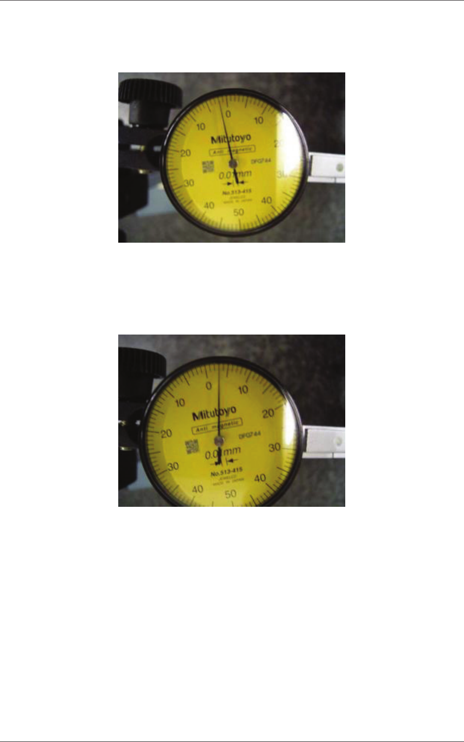
(4) Check the reading of the pry-type dial gauge.
Example 1
: When the dial gauge reads "-0.02 mm" as shown
below, it is required to enter the offset value "20".
Fig. D59
Example 2
: When the dial gauge reads "+0.03 mm" as shown
bellow, it is required to enter the offset value "-30".
Fig. D60