JO-116-001_w.pdf - 第60页
3-1 1 JO-1 16 1 105-001 4. "T ype Setting" Window (1) Outline of Each T ype Data Program Nos. (1 to 100) These Nos. represent the type Nos. of the type data and are used to change the type data. Up to 100 types…
3-10
JO-116
1105-001
4. "Type Setting" Window
4. "Type Setting" Window
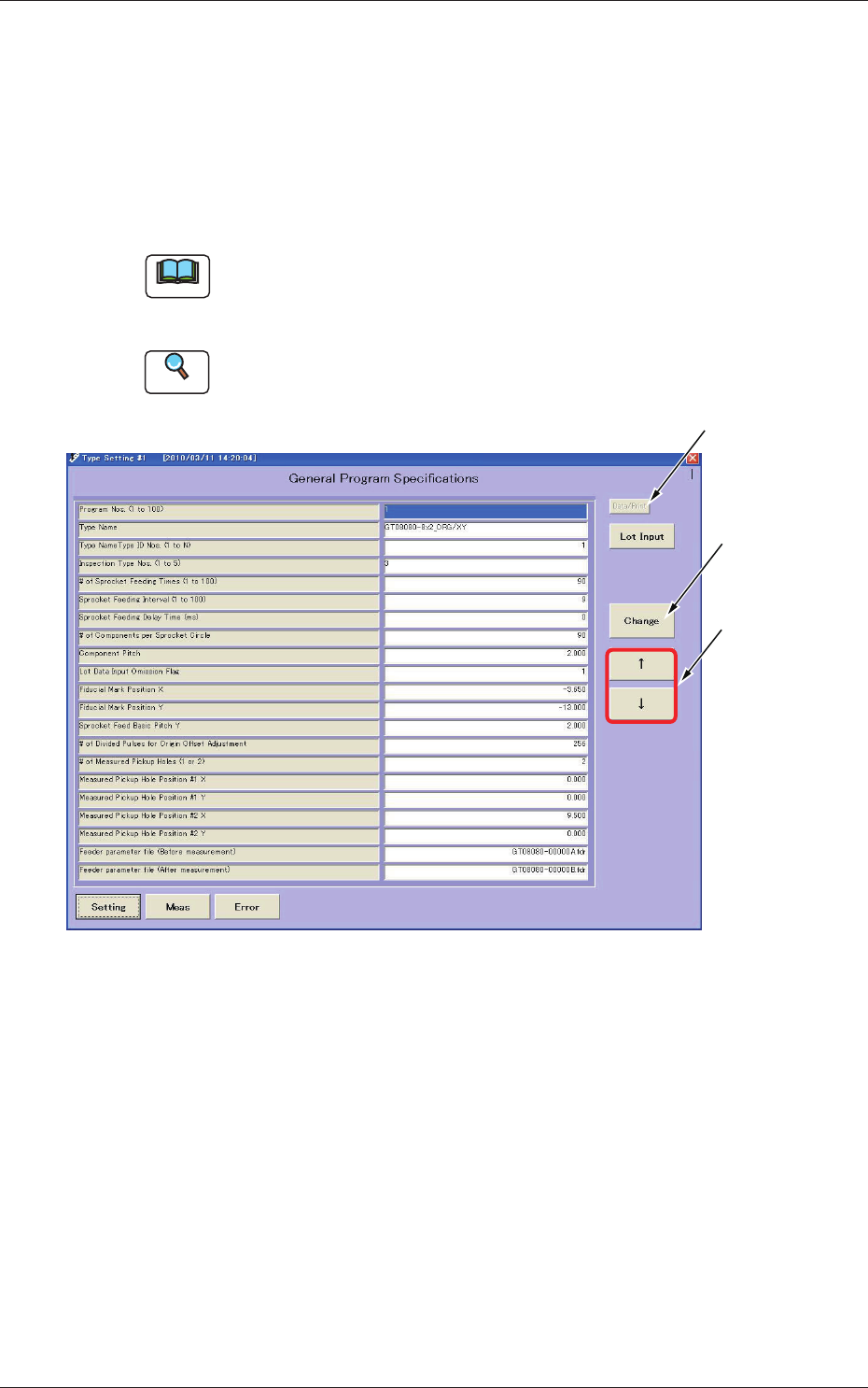
Displayed is the type data.
When you press the [Setting] button at each window, the "Type Setting"
window opens.
Pressing the [Setting] button again opens the "Type Listup" or the "Type
Setting" window or vice versa.
Note
Only "Administrator" or "Power User" can change each executable data in
this window.
"User" can execute only the selection of types.
Reference
Refer to "1. Administrative Authority Change" in "Section 3" for details.
Used to print
the type data.
Used to change
the set value.
Used to move
the cursor.
Fig. C12 "Type Setting" Window

3-11
JO-116
1105-001
4. "Type Setting" Window
(1) Outline of Each Type
Data Program Nos. (1 to 100)
These Nos. represent the type Nos. of the type data and are used to
change the type data.
Up to 100 types (from 1 to 100) can be registered.
Type Name
It is advisable that a name starting with the feeder type No. should be
entered and the type (contents) can be identied easily.
A type can be selected according to the type name in the "Type Listup"
window.
Up to 40 alphanumeric characters can be used as an ID.
As the former string of characters (feeder type name) is searched during
automatic type selection, it is recommended that a title name should be
entered starting with the type name.
Type Name Type ID Nos. (1 to N)
This represents the regulated ID No. for type display regulation.
A value "1 to N" is used to specify the type.
"N" is separately specied by setting the type-based classication list.
Inspection Type Nos. (1 to 5)
Specify the number which represents the contents of inspection.
A number "1 to 5" can be set.
1:
Inspection of Lane Origin Offset Adjustment
2:
Inspection of Fiducial Mark Positioning
3:
Simultaneous Inspections (above-described "1" and "2")
In the case of the following tape feeder models for SIGMA-G4/G5 and
GXH Series inspection type No. 4 or 5 is to be designated.
GT/GD-2808 / 28083
4:
Simultaneous and complicated lane origin offset adjustment and
recognition mark position adjustment and sprocket offset adjustment
operations.
5:
For the lane origin offset adjustment, recognition mark position
adjustment and sprocket offset adjustment, the already set values are
reected.
# of Sprocket Feeding Times (1 to 100)
Specify the maximum value that represents the number of sprocket
feeding times for inspection.
A value "1 to 100" can be set.
Sprocket Feeding Interval (1 to 100)
Specify the number of sprocket feeding times required after the
inspection is executed.
A value "1 to 100" can be set.

3-12
JO-116
1105-001
4. "Type Setting" Window
# of Components per Sprocket Circle
Specify the number of components (pickup holes) per sprocket circle. A
value "1 to 500" can be set.
Ref.:
The set number of components are used for graphical display.
Component Pitch (mm)
Specify the component (pickup hole) pitch in "mm".
A value "0.001 to 64.000" can be set.
Ref.:
The set value is used for graphical display.
Lot Data Input Omission Flag (0 or 1)
The set ag is used to omit the entry of lot data when the inspection is
executed.
0:
Not Omitted (Displayed and Specied at Each Inspection)
1:
Omitted (Only Displayed Initially and Omitted after Specication)
Fiducial Mark Positions X and Y
Specify the positional coordinates of the ducial mar according to the
position based on Master Reference Position 1.
Sprocket Feed Basic Pitch Y
Specify the tape feeding pitch per sprocket pin.
(Sprocket Feeding Distance at Transfer of Number of Divided Pulses on
Next Item)
A value "0.001 to 8.000" can be set.
# of Divided Pulses for Origin Offset Adjustment
The entry range of origin offset must also be specied here.
The offset value for adjustment is calculated based on an error between
the specied value and the feed basic pitch
A value "1 to 16384" can be set.
# of Measured Pickup Holes (1 or 2)
Specify the number of pickup hole rows (lanes).
A value "1" or "2" can be set.
Measured Pickup Hole Position #1 X and Y/Measured Pickup
Hole Position #2 X and Y
Specify the pickup hole inspection position according to the position
based on Master Reference Position 1.
When the number of rows (previous item) is "1", no parameter can be
specied for Pickup Hole Position 2.