JO-116-001_w.pdf - 第70页
3-21 JO-1 16 1 105-001 6. "Measurement" Window [4] [Chart] button When pressed, this button opens the "Chart" window . [5] Display Control Button When pressed, this button opens or closes the image wi…
3-20
JO-116
1105-001
6. "Measurement" Window
6. "Measurement" Window
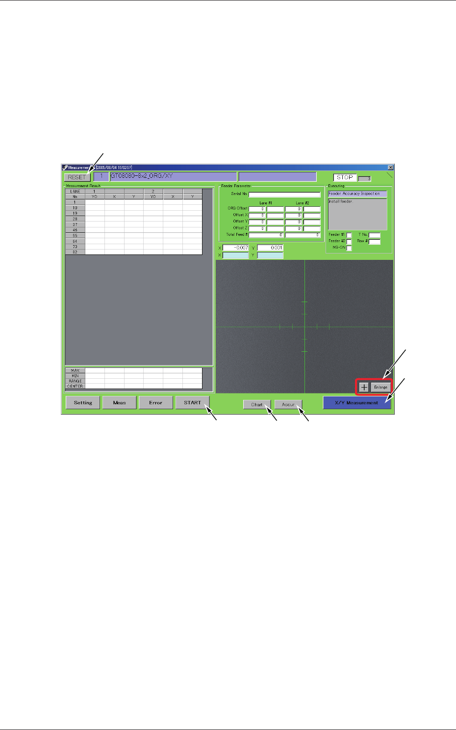
This window can be used to execute an accurate inspection of the feeder,
view the results of the inspection, and create an accuracy table.
When you press the [Meas] button located at the bottom of each window, the
"Measurement" window opens.
Description of Each Button
[5]
[6]
[3]
[4][1]
[2]
Fig. C15 "Measurement" Window
[1] [START] button
When pressed, this button starts the measurement.
While the measurement is performed, the label on the button is changed
to "STOP". When the [STOP] button is pressed, the measurement is
interrupted temporarily.
[2] [RESET] button
This represents that the measurement is interrupted. This appears when
the measurement is interrupted temporarily with the [STOP] button in
[1].
[3] [Accur] button
When pressed, this button opens the "Accuracy Measurement Table"
window.
3-21
JO-116
1105-001
6. "Measurement" Window
[4] [Chart] button
When pressed, this button opens the "Chart" window.
[5] Display Control Button
When pressed, this button opens or closes the image window.
[6] [X/Y Measurement] button
The current X and Y positions are regarded as the results of each
measurement.
Description of Each Displayed Items
[7]
[6]
[3]
[5]
]2[ ]1[
[8][9]
[4]
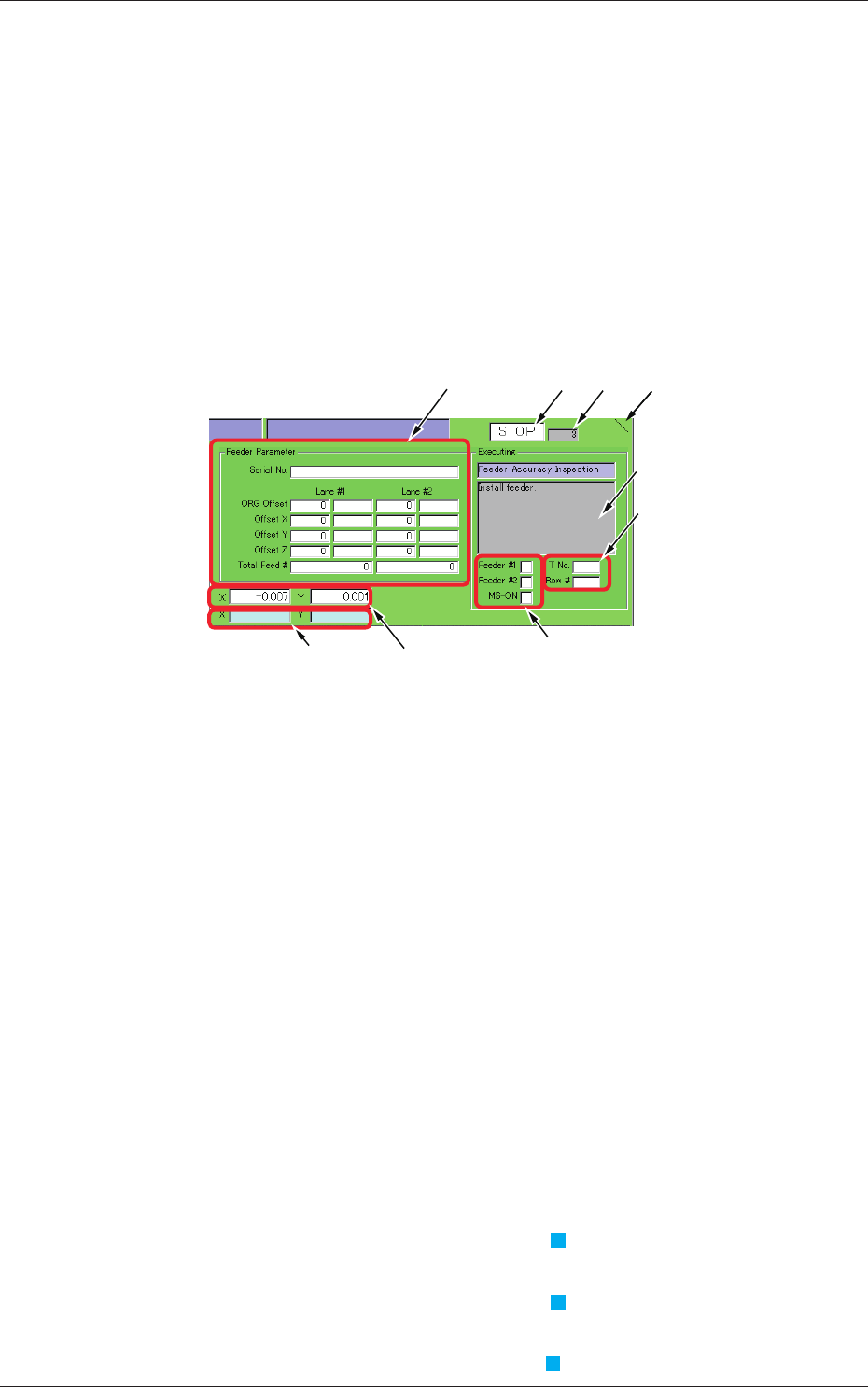
Fig. C16
[1] Display Mark
The displayed mark will be spinning while this program is running.
[2] Sequence Speed
Displayed is the referential value of the sequence speed.
Ref.:
This value changes greatly according to the processed contents.
[3] Automatic Running Mode
Displayed is the automatic running mode. [RUN], [PAUSE], [STOP].
[4] Running Mode
Displayed are the current execution mode and a message.
[5] Feeder1, Feeder2, MS-ON
Displayed is the status of each signal that indicates whether or not
feeders are installed.
The box beside "Feeder 2" turns light blue (
) when the feeder is
installed.
The box beside "Feeder 1" turns light blue ( ) when the power is
turned "ON".
The box beside "MS-ON" turns light blue ( ) in the "Clamp" mode.
3-22
JO-116
1105-001
6. "Measurement" Window
[6] T No., Row #
Displayed are the lane and pickup hole Nos. under inspection.
[7] Feeder Parameter
Displayed are the feeder parameters.
[8] Table X/Y
Displayed are the current X/Y coordinates (address) of the table.
[9] Measurement Address X/Y
Displayed are the X/Y coordinates (address) of the measurement
address (design value).
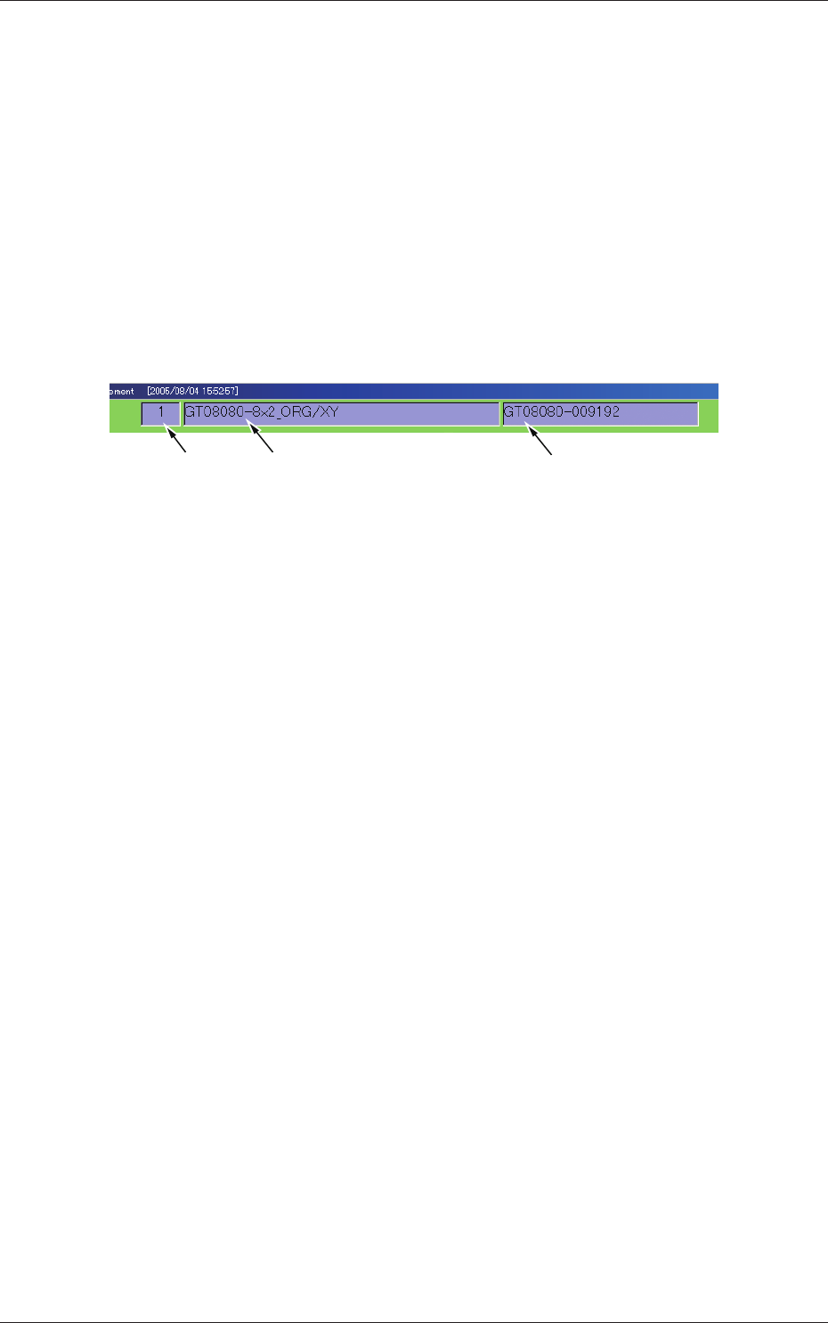
Type No. Type Name Serial No.
Fig. C17