Operating Manual.pdf - 第44页
4022 591 960 62 Operating Manual 02.0 2 FCM Mu ltif lex 42 New Progr am Selection 4. The sequence for rem ovin g the MBS is fr om Ru n out side t o Run in si de FIGURE 66 5. R em o v e the suppor t strips an d place it i…
4022 591 96062 Operating Manual
02.02 FCM Multiflex 41
New Program Selection
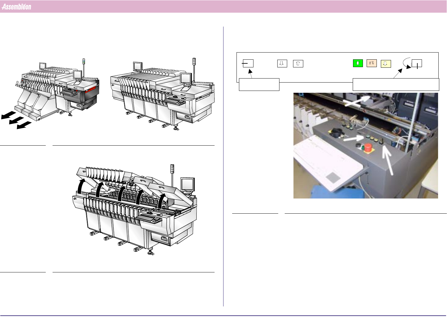
8.2 Exchange MBS Carriers and Set Transport Width
1. Remove trolleys
FIGURE 63
2. Open all placement modules, Run-in and Run-out covers
FIGURE 64
3. Move the transport all the way to the rear end using the push button
FIGURE 65
0
1
Off situation
Service key Width/Height adjustment key
Height
Width
Off
Height
Width
4022 591 96062 Operating Manual
02.02 FCM Multiflex 42
New Program Selection
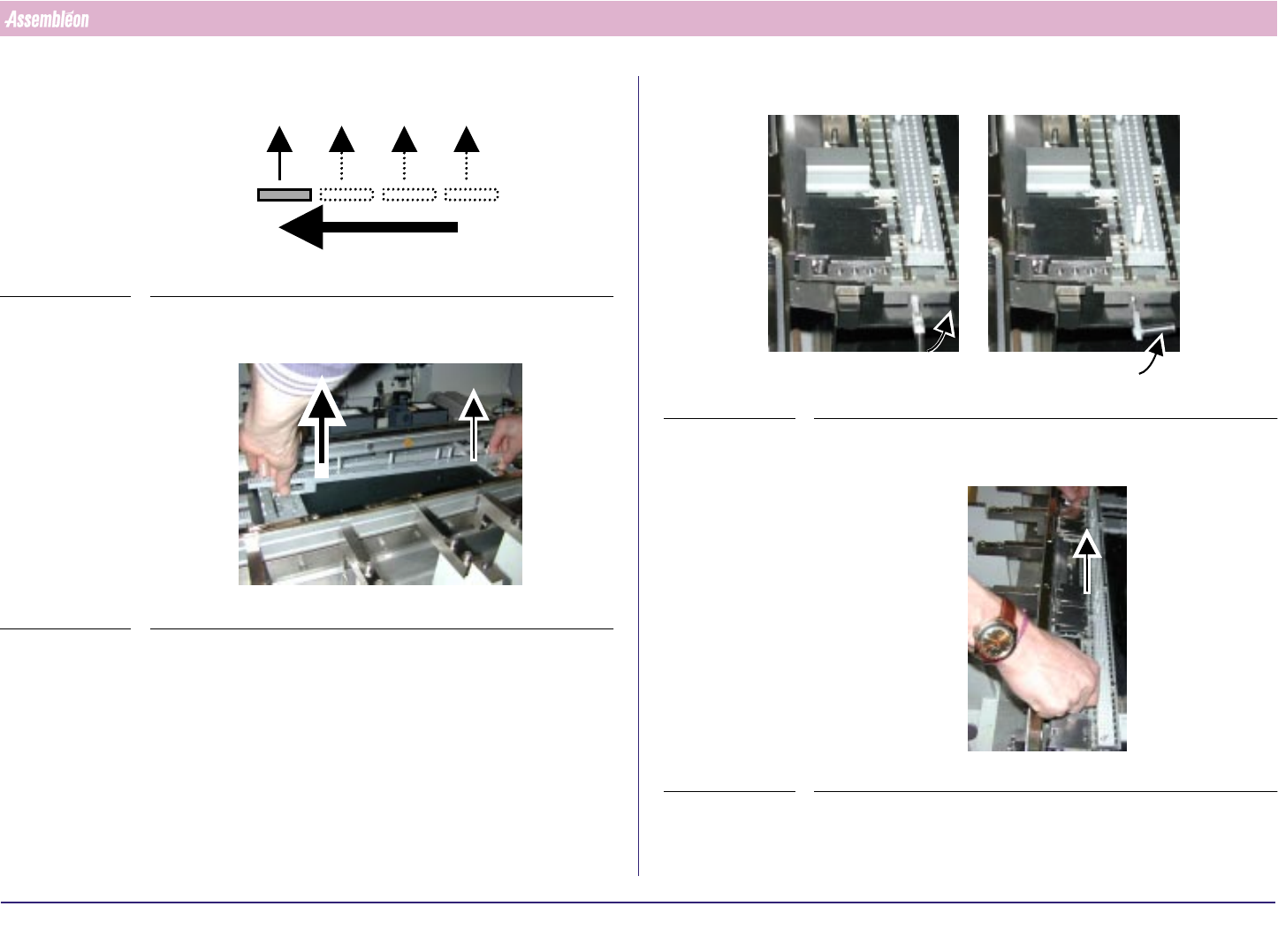
4. The sequence for removing the MBS is from Run out side to Run in side
FIGURE 66
5. Remove the support strips and place it in its storage case
FIGURE 67
6. Lift the quick lock handle(s) of the last (section 4) base interface
FIGURE 68
7. Remove the positioning strip(s) and place it in its storage case
FIGURE 69
4022 591 96062 Operating Manual
02.02 FCM Multiflex 43
New Program Selection
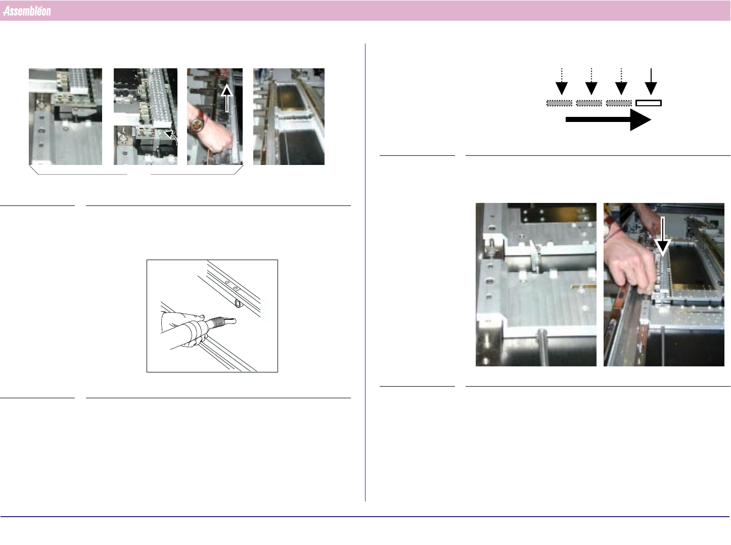
8. Repeat step 5. until 6. to empty all sections (3, 2 and 1)
FIGURE 70
9. Clean the whole board-transport area so that all wasted components are
removed
FIGURE 71
x3
10.The sequence for placing /installing MBS is from Run in to Run out side
FIGURE 72
11.Get, from its storage case, the new complete positioning strip for section
1 and place it at the correct position on the base interface section 1
FIGURE 73