Operating Manual.pdf - 第73页
4022 591 960 62 Operating Manual 02.0 2 FCM Mu ltif lex 71 Err or Handling 8. If the err or could n ot be reco vered after ’ Ret r y ’ or ’ Retry all ’ the f ollo win g Screen appears. SCREEN 55 9. Sel ect ’ OK ’ t o go …
4022 591 96062 Operating Manual
02.02 FCM Multiflex 70
Error Handling
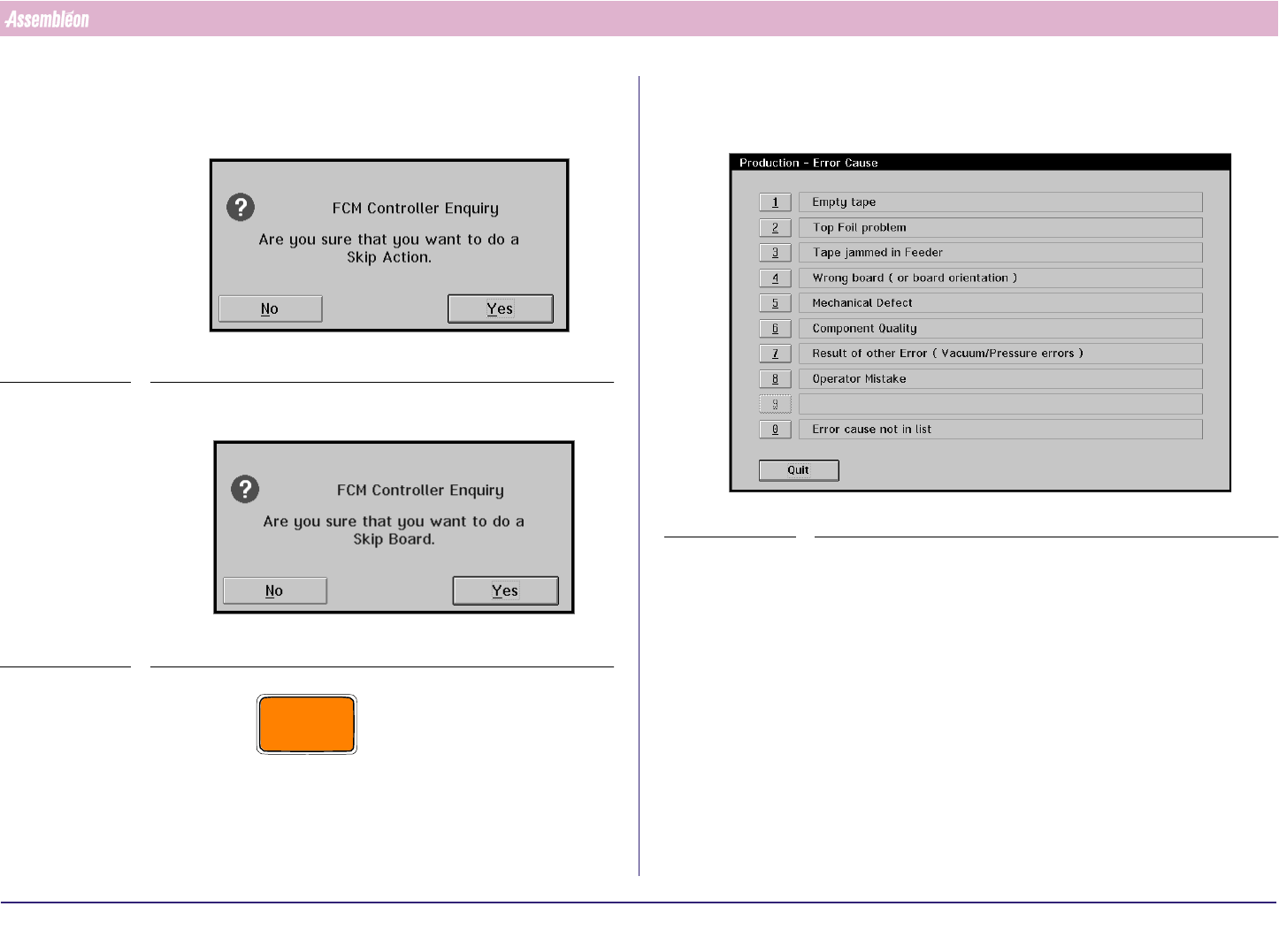
6. If the problem can not be solved:
• Select ‘Skip action [F11]’ to skip the selected action. The FCM stops
this component placement on the board.
SCREEN 52
• Select ‘Skip board [F12]’ to stop further production of this board.
SCREEN 53
CAUTION
SELECTING ‘SKIP ACTION’ OR ’SKIP BOARD’ LEADS TO INCOMPLETE
BOARDS AT THE FCM RUN-OUT. THE MESSAGE ‘SUSPECTED BOARD IN
RUN-OUT SECTION’ APPEARS. REMOVE OR MARK THE BOARD.
7. The Error Cause Dialogue appears if this function has been enabled in the
’MIS-Parameters’. Select an error cause. After selection the error recovery
action will be performed.
SCREEN 54
4022 591 96062 Operating Manual
02.02 FCM Multiflex 71
Error Handling
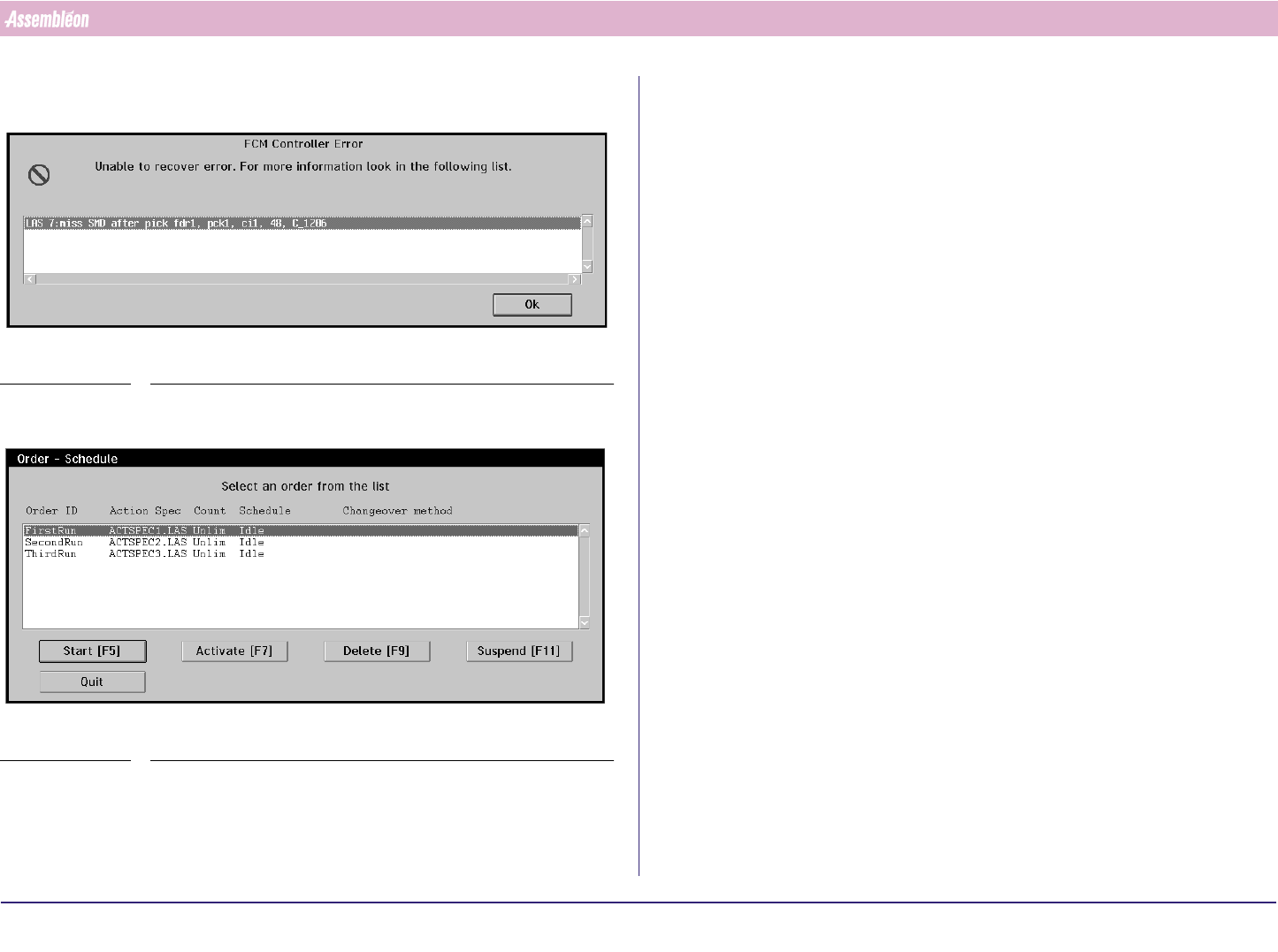
8. If the error could not be recovered after ’Retry’ or ’Retry all’ the following
Screen appears.
SCREEN 55
9. Select ’OK’ to go back to the ’Error Recovery Dialogue’.
SCREEN 56
10.In case the problem can not be solved, call for assistance.
11.2 Possible Errors and Solutions
Most frequent occurring errors:
1. Miss SMD after pick
2. Misalign SMD
3. Pick-up Error / Y pick offset too large
4. Feeder problem.
5. Laser beam obstructed
6. Cal high or cal low surpassed.
7. Unexpected board in run in section
8. Board stuck in run in or run out section:
9. Fiducial measurement fail
Their most likely solutions are:
1. Miss SMD after pick
■ Empty feeder.
■ Too many empty pockets in tape.
■ Wrong nozzle type.
■ Wrong component type.
■ Dirty nozzle.
2. Misalign SMD
■ Wrong component type.
3. Pick-up Error / Y pick offset too large
■ Feeder trolley not mounted properly.
■ Feeder not mounted properly.
■ Index on feeder not correct.
4022 591 96062 Operating Manual
02.02 FCM Multiflex 72
Error Handling
4. Feeder problem.
See feeder manual.
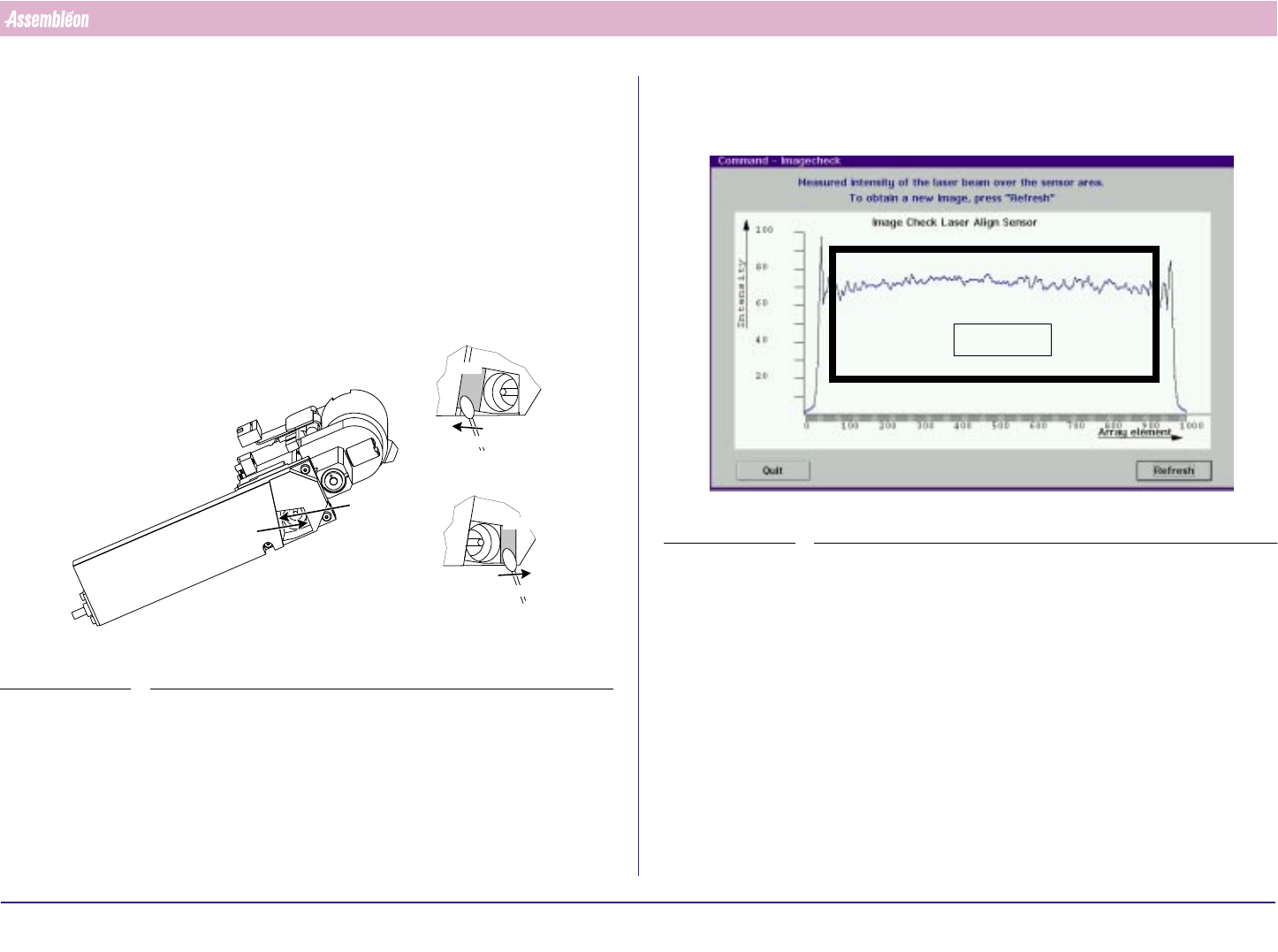
5. Laser beam obstructed
■ Dirty laser window: clean it:
Instruction:
a) Remove the dust on windows A & B with a Q-tip. Move the Q-tip from
the top to the bottom of the window and then out of the laser unit
(see FIGURE 113 on page 68).
FIGURE 115 Cleaning the laser window
b) Clean the laser window with a Q-tip and a little reagent grade
isopropyl alcohol. Use the same top-to-bottom movement (see step
a). Always use a clean part of the Q-tip.
view A
view B
Q-tip
Q-tip
Window
Window
view A
view B
c) Dry the treated surface with a Q-tip.
After cleaning the window check the PPU laser beam with the image
check function (see SCREEN 57 on page 72)
SCREEN 57 Image display
d) If results are not satisfactory repeat from step b onwards.
6. Cal high or cal low surpassed.
■ Wrong nozzle type.
■ Dirty nozzle.
■ Vacuum problems
Area of interest