Operating Manual.pdf - 第8页
4022 591 960 62 Operating Manual 02.0 2 FCM Mu ltif lex 6 CHAPTER 2 Gener al Ma chine Inf ormatio n 2.1 Front Side Items FIGURE 3 A B Poi n t e r F7 F8 F11 F12 Delete End Pg Dn Scroll Lock Num Lock /* - Enter + F1 F2 F9 …
4022 591 96062 Operating Manual
02.02 FCM Multiflex 5
Safety
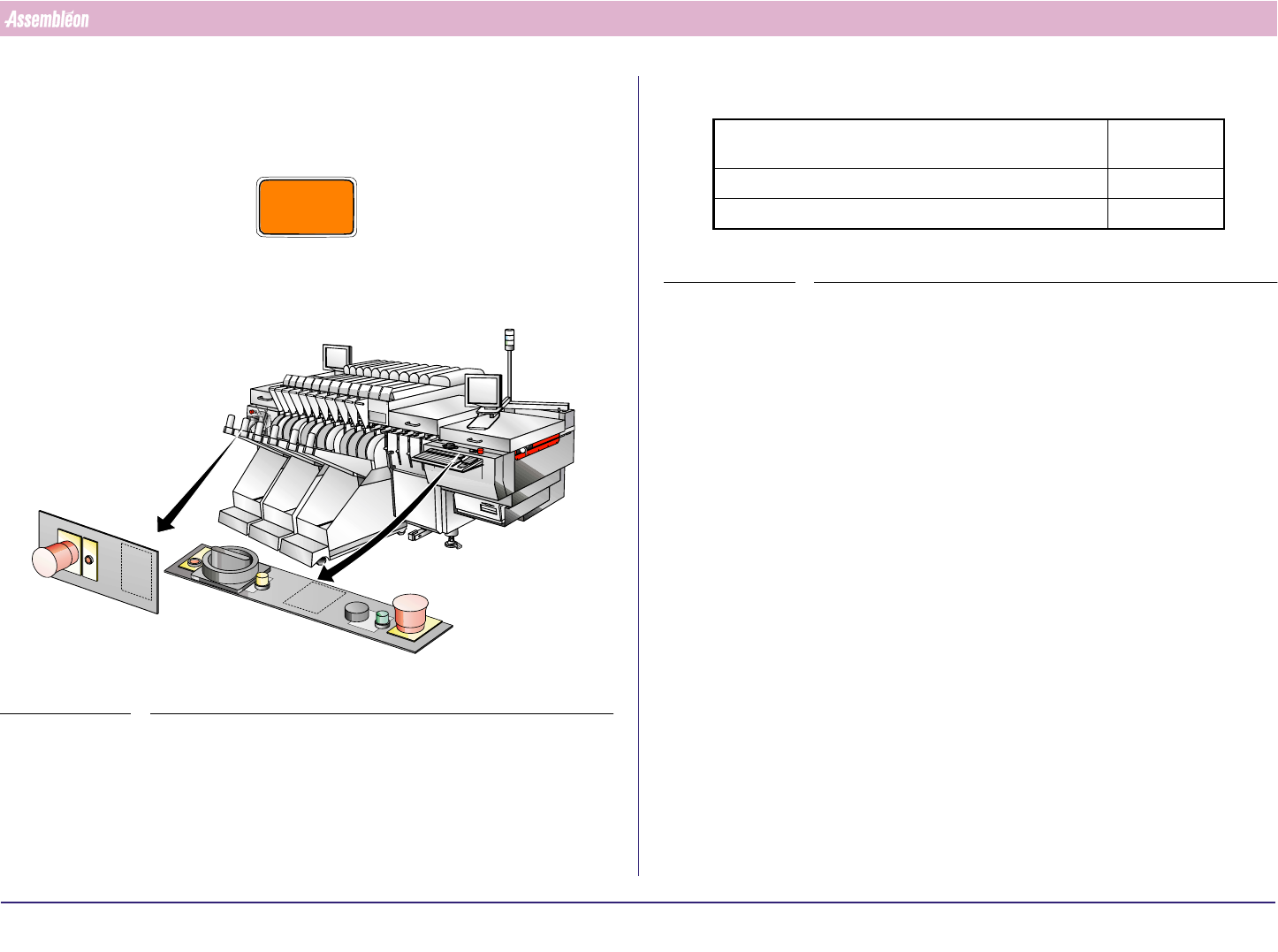
1.7.2 Emergency Stop Button
In case of an emergency push on one of the red emergency stop buttons to
immediately remove all power to the FCM actuators.
CAUTION
AN EMERGENCY STOP MAY LEAD TO INCOMPLETE PRODUCTS
Pull the red emergency stop button to release the emergency.
FIGURE 2
1.8 Noise Level
TABLE 1
1.9 Liability
Assembléon will not be liable for any costs, damages or personal injuries if
the FCM is not used according to the safety rules given in this operating
manual.
1.10 Location of the Operating Manual
The operating manual must be located close to the FCM. This enables users
to have easy access to the relevant section.
Average sound-pressure level measured at 3 operator
positions at height = 1.5 m and distance = 1 m
≤ 79 dB(A)
Sound pressure at operator’s position ≤ 78 dB(A)
Average environmental noise level during measurement 53 dB(A)
4022 591 96062 Operating Manual
02.02 FCM Multiflex 6
CHAPTER 2 General Machine Information
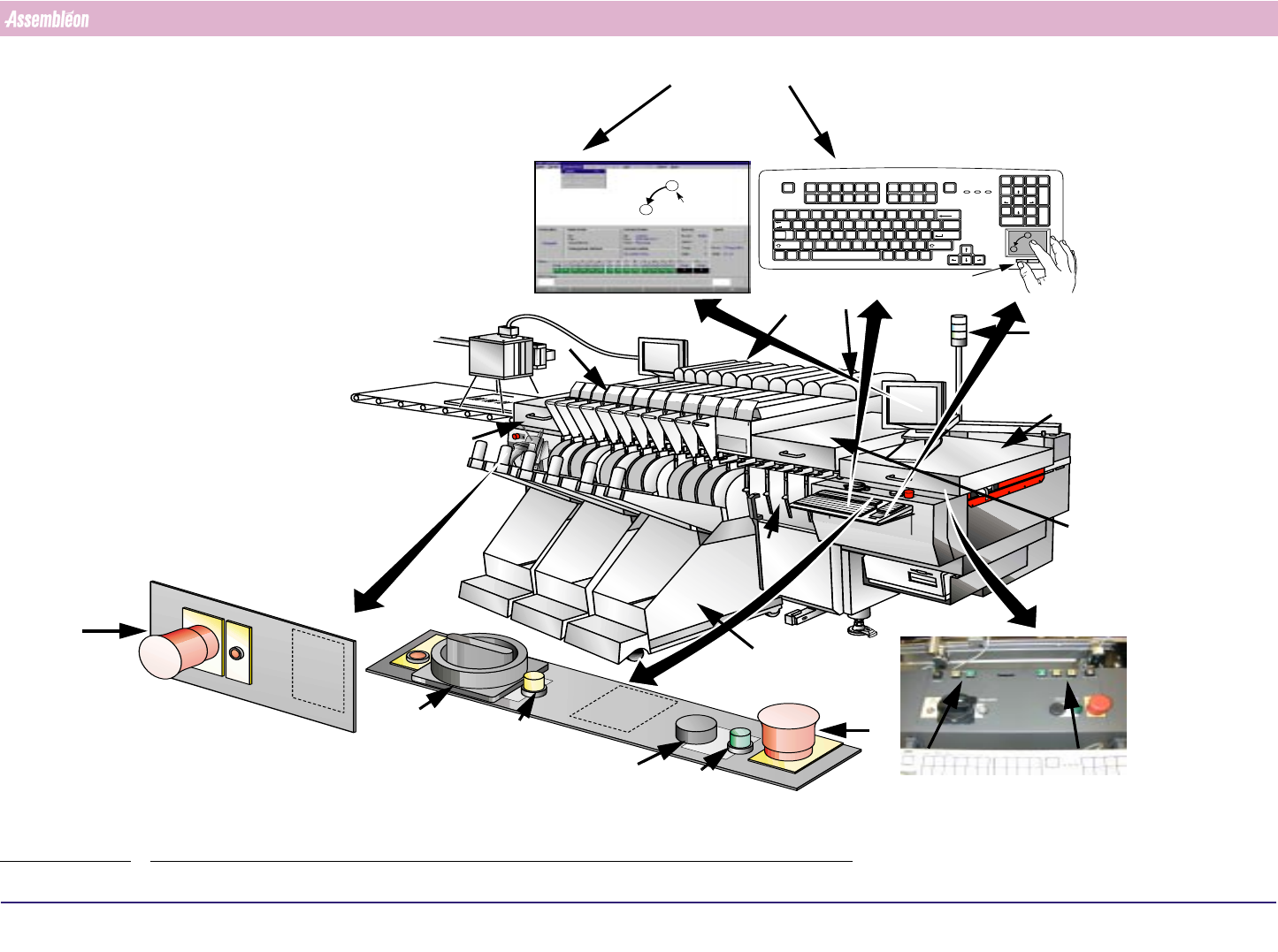
2.1 Front Side Items
FIGURE 3
A
B
Pointer
F7 F8 F11 F12
Delete End Pg Dn
Scroll
Lock
Num
Lock
/*
-
Enter
+
F1 F2
F9 F10
F3 F4 F5 F6
Insert Home Pg Up
Print
Screen
SysRq
Pause
Break
Esc
`
1234567890- =
~!@#$%^&* ()_+
Q
Tab
Caps
Lock
WER T YU I OP
789
456
123
Home Pg Up
End Pg Dn
0
Ins
[]
{}
\
|
ASDFGH J
ZXCVBNM
KL
;'
:"
Enter
,./
Shift
<>?
Backspace
CtrlAlt CtrlAlt
Shift
Del
.
A
B
Left control
button
BVM monitor
Status indicators
White: idle
Blue: error
Green: running
Monitor
Main
Emergency
stop
Emergency
stop
Emergency Panel (run-in)
Main power
phase indicator
Main switch panel (run-out)
Servo
power
Servo
power
Feeder trolley
CLM
WVM
Width adjustment
buttons and key
switch
Z-adjustment
BI module
Run-out
Run-in cover
Safety cover
Safety cap
(1 or 4
positions
Can also be
selected with the
matching function
key(F1....F12
The pointer on the
monitor can be moved by
moving a finger over the
touch pad
An item on the monitor
can be selected by tapping
on the touch pad or
pressing the left control
button below the touch
pad
4022 591 96062 Operating Manual
02.02 FCM Multiflex 7
General Machine Information
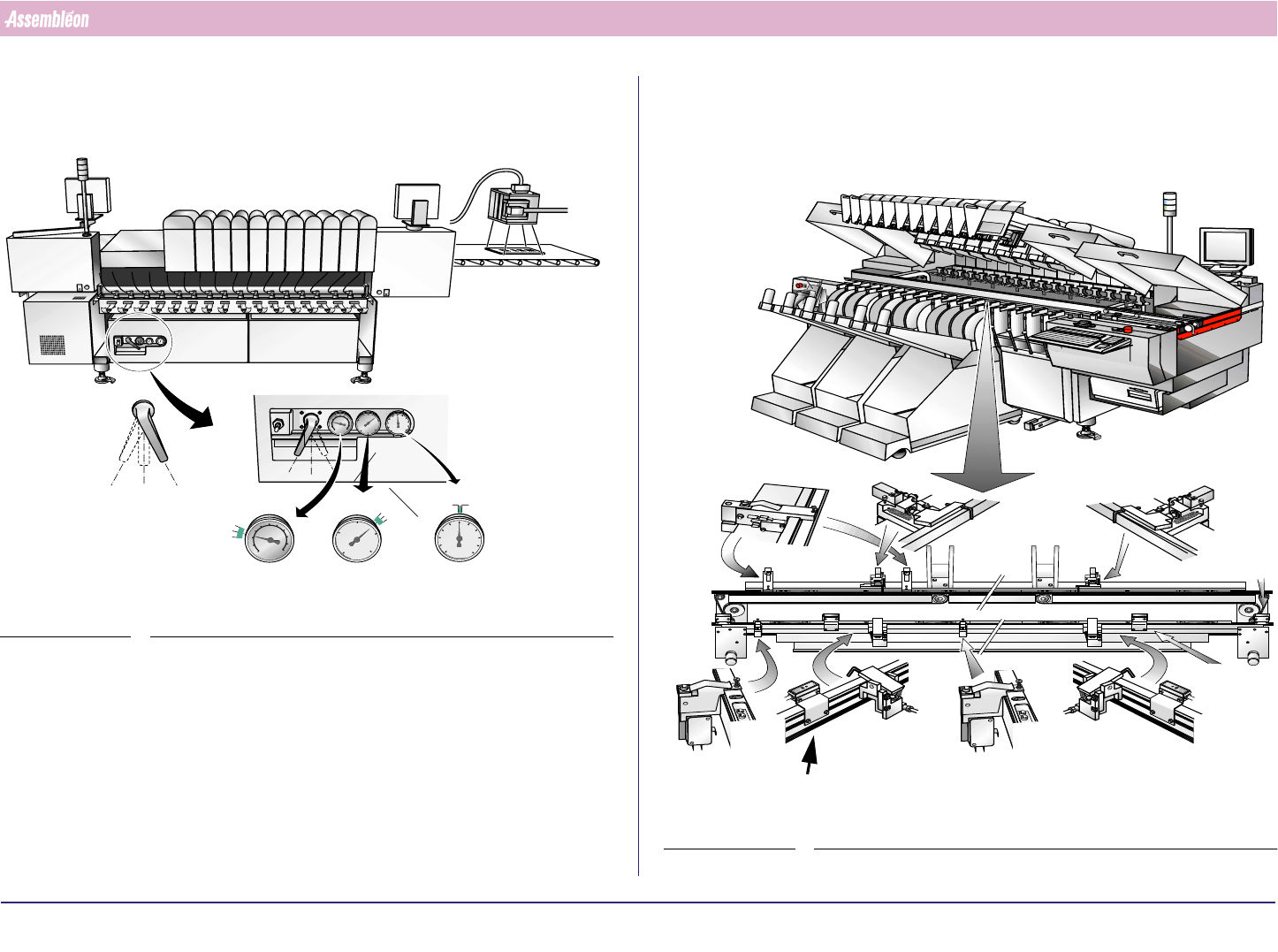
2.2 Rear Side Items
FIGURE 4
5.8 bar
5.6 bar
2.7 bar
2.5 bar
-0.82 bar
-0.74 bar
5.7 bar
2.6 bar
-0.77 bar
Main air valve
Release air
pressure
Open
Closed
Vacuum gauge
Pressure gauges
2.6 bar 5.7 bar
2.3 Transport Items
FIGURE 5
Board in position
detector rear
Run-in stopper
rear
Run-out stopper
rear
Run-in stopper
front
Run-out stopper
front
Board in position
detector front
Board
detector
run-in
Board in
position
detector front
Low speed detector
Board anti
collision
detector
Board left
machine
detector